

In this step, only upload the image and set the scale (enter the actual plan size). Do not use any other areas or buttons not described in this manual.
1) Registering the Building
Open the [Building List] menu and click the [+ Register Building] button at the top right of the screen.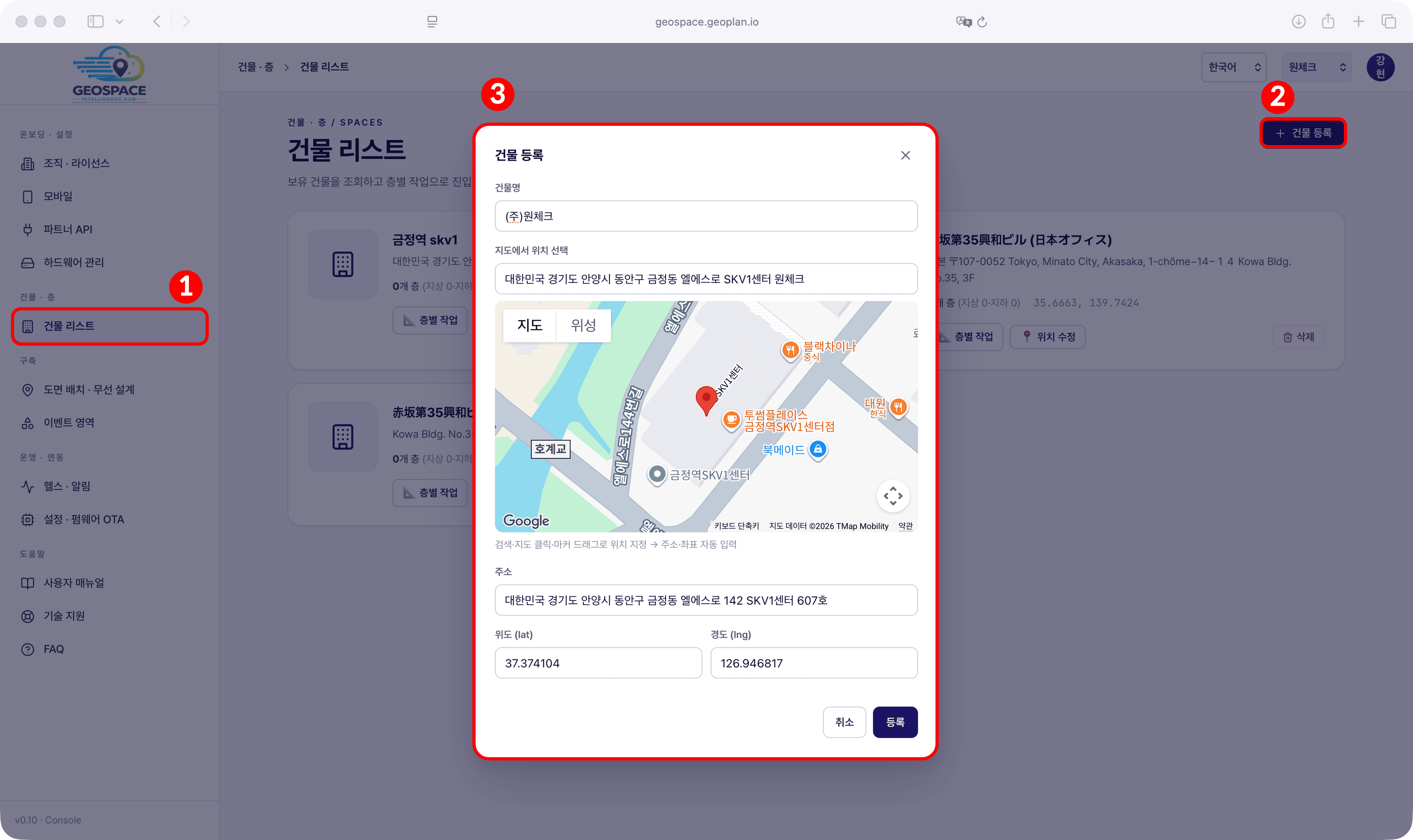
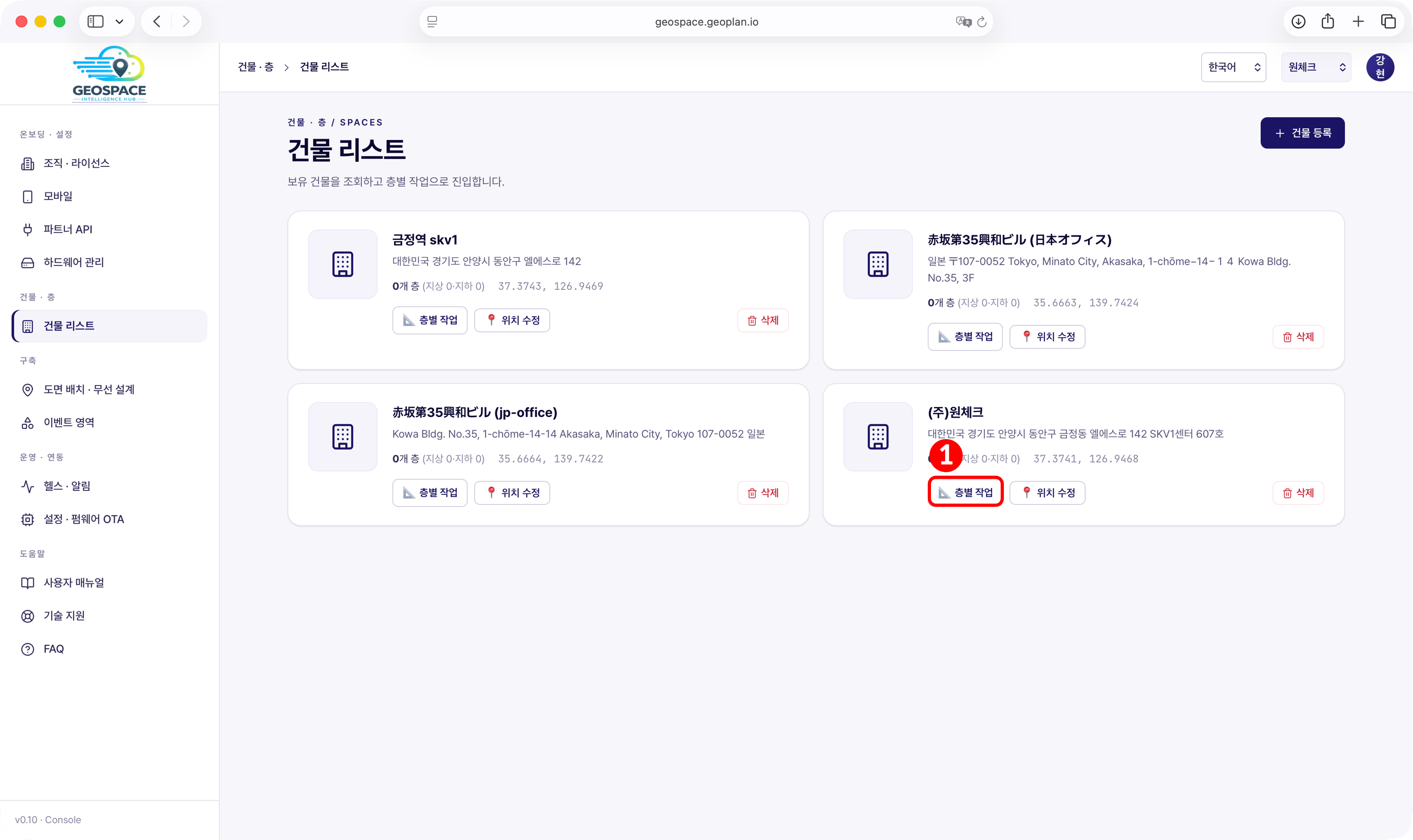
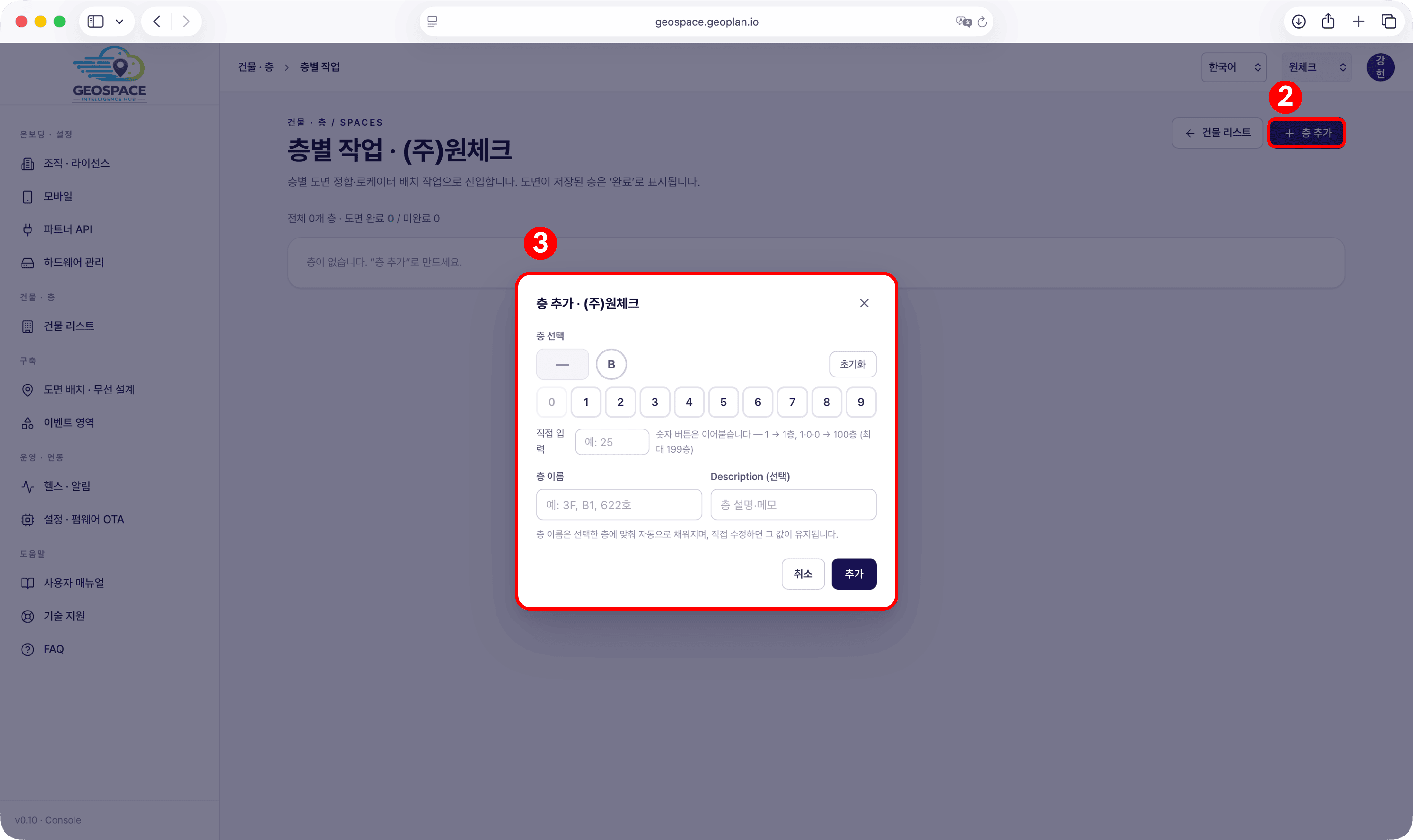
2) Registering Floors
3) Registering and Setting Up the Floor Plan
If you have no plan to register, you can skip this section and proceed to
4. On-Site Locator Installation. Locator positions are then entered
directly as coordinates in 6. Activating Positioning. In that case
the floor shows as ‘Incomplete’ instead of ‘Plan Complete’ in the floor list, which does not
block the following steps.
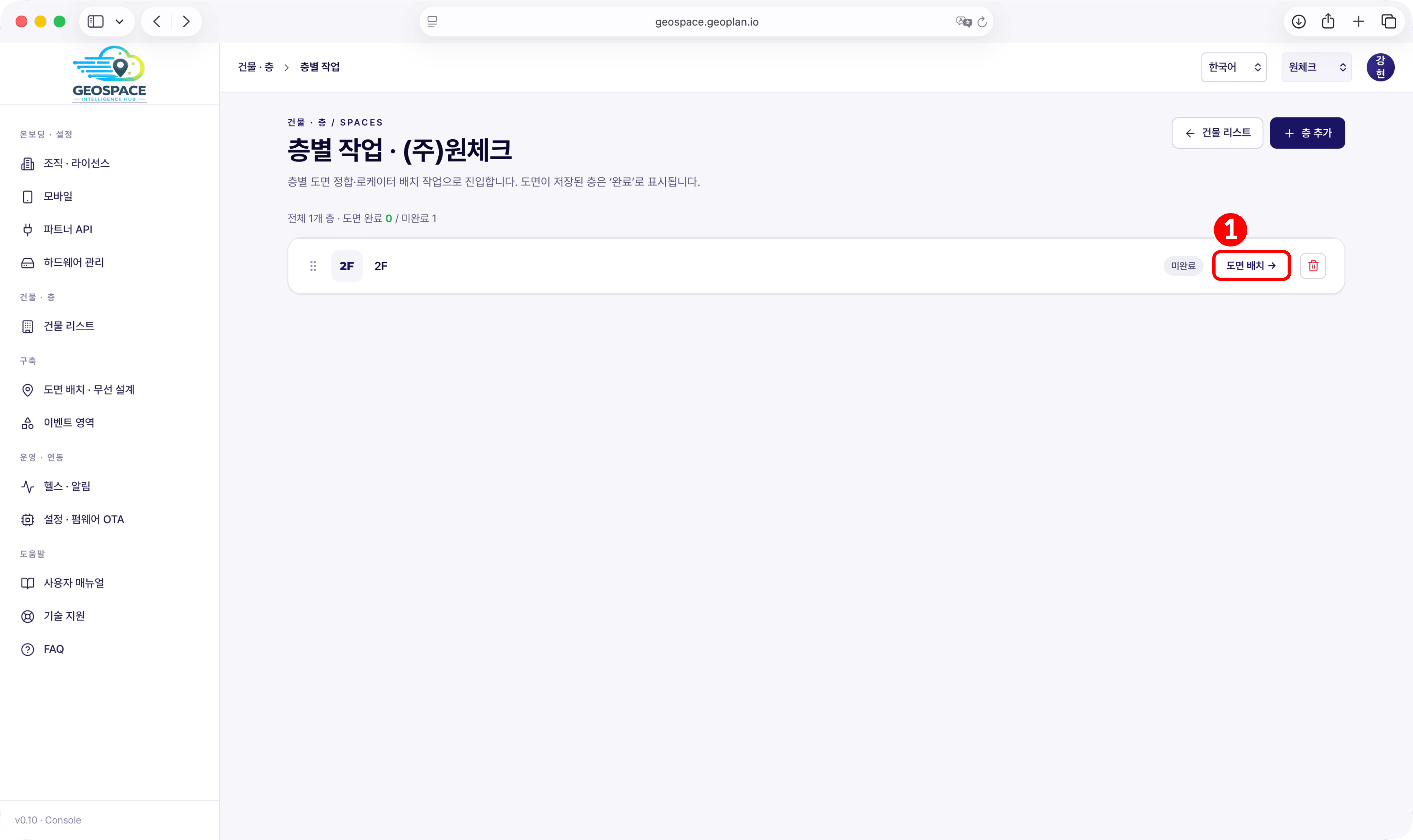
- In the floor list, click [Plan Placement →].
-
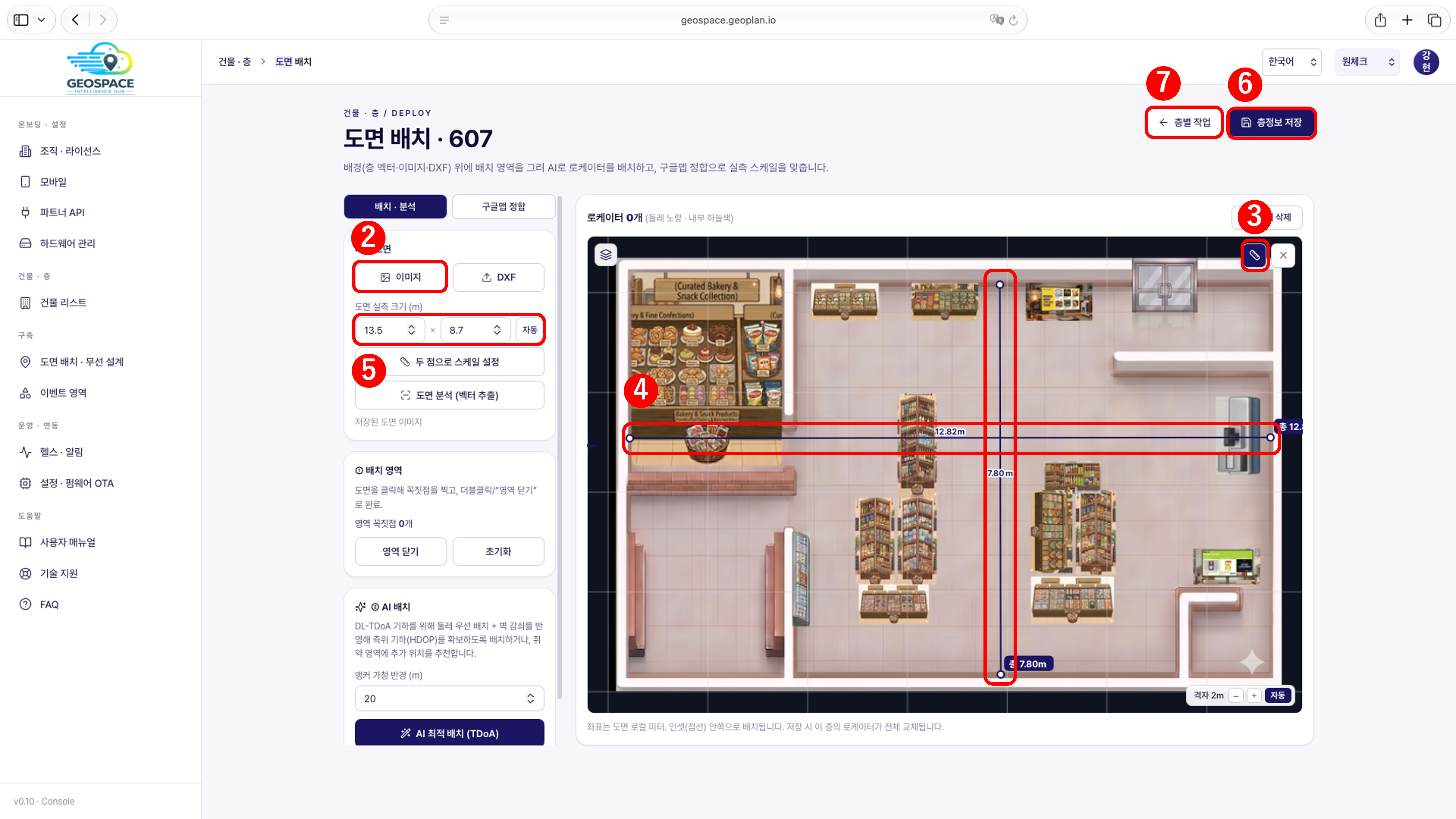
Click the [Image] button and upload the plan file (PNG or JPG), then
enter the measured width and depth (m) of the space in ‘Actual plan size’.
- When the upload completes, the image file name, size, and pixel dimensions (px), along with the measured values matching the initial image, appear as a label under the [Analyze Plan] button.
- Click the tape measure (distance measurement) button at the top right of the plan.
-
Click two points on the plan in turn to display the distance between them.
Measure a stretch whose real distance you know (wall to opposite wall, for example) and check that it matches the measured value.
- Click the start point of the stretch, click the end point, then press Enter to display the straight-line distance between the two points on the plan.
- Measure once horizontally and once vertically.
- The measured distance stays on the plan until you end measurement, so you can keep it on screen while checking and adjusting values. When done, click the [X] button next to the tape measure or press ESC to finish.
Why verify by measuring
‘Actual plan size’ applies to the full width and depth of the plan image. If the image includes margins outside the actual space, the image size and the actual space size differ, and distances on the plan can drift from the measured values. That is why you measure a stretch with a known real distance and adjust if it is off.
‘Actual plan size’ applies to the full width and depth of the plan image. If the image includes margins outside the actual space, the image size and the actual space size differ, and distances on the plan can drift from the measured values. That is why you measure a stretch with a known real distance and adjust if it is off.
-
If the measured distance differs from the actual value, re-enter ‘Actual plan size’ to match
the measured value, or adjust the scale with [Set Scale with Two Points].
- The plan image’s proportions adjust automatically to the entered values.
- When you enter the width, the depth is calculated automatically from the image’s aspect ratio. If you edited the depth manually, click [Auto] to recalculate it from the width.
- Click [Save Floor Info] at the top right to save the plan settings.
- Click the [Floor Tasks] button at the top right to return to the floor list.
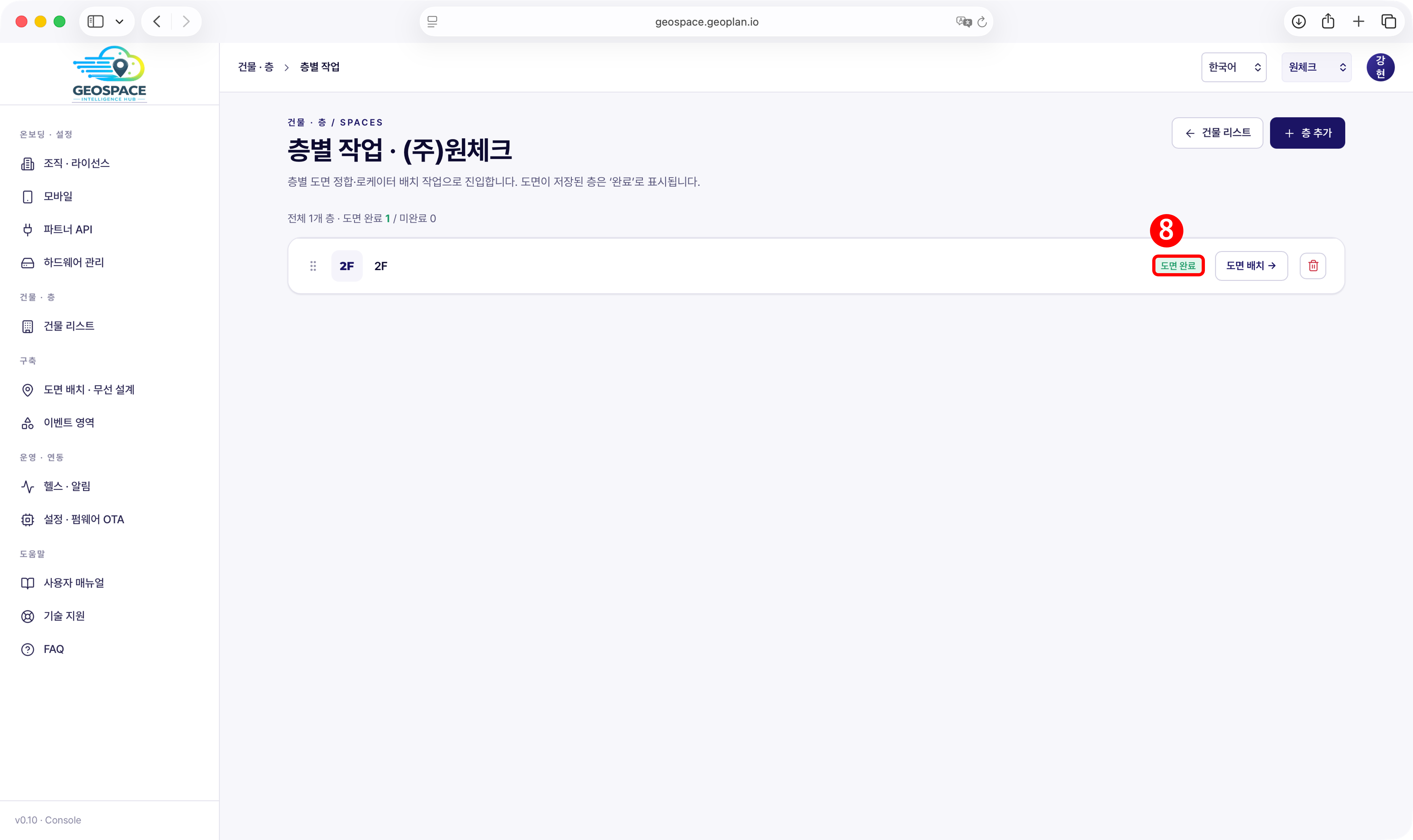
- Confirm the floor shows as ‘Plan Complete’.
Checklist
Once all items below are confirmed, you can move on to the next step.