

In this step, only perform hardware selection, position placement, and cluster setup.
Do not use any other areas or buttons not described in this manual.
Menus used in this step
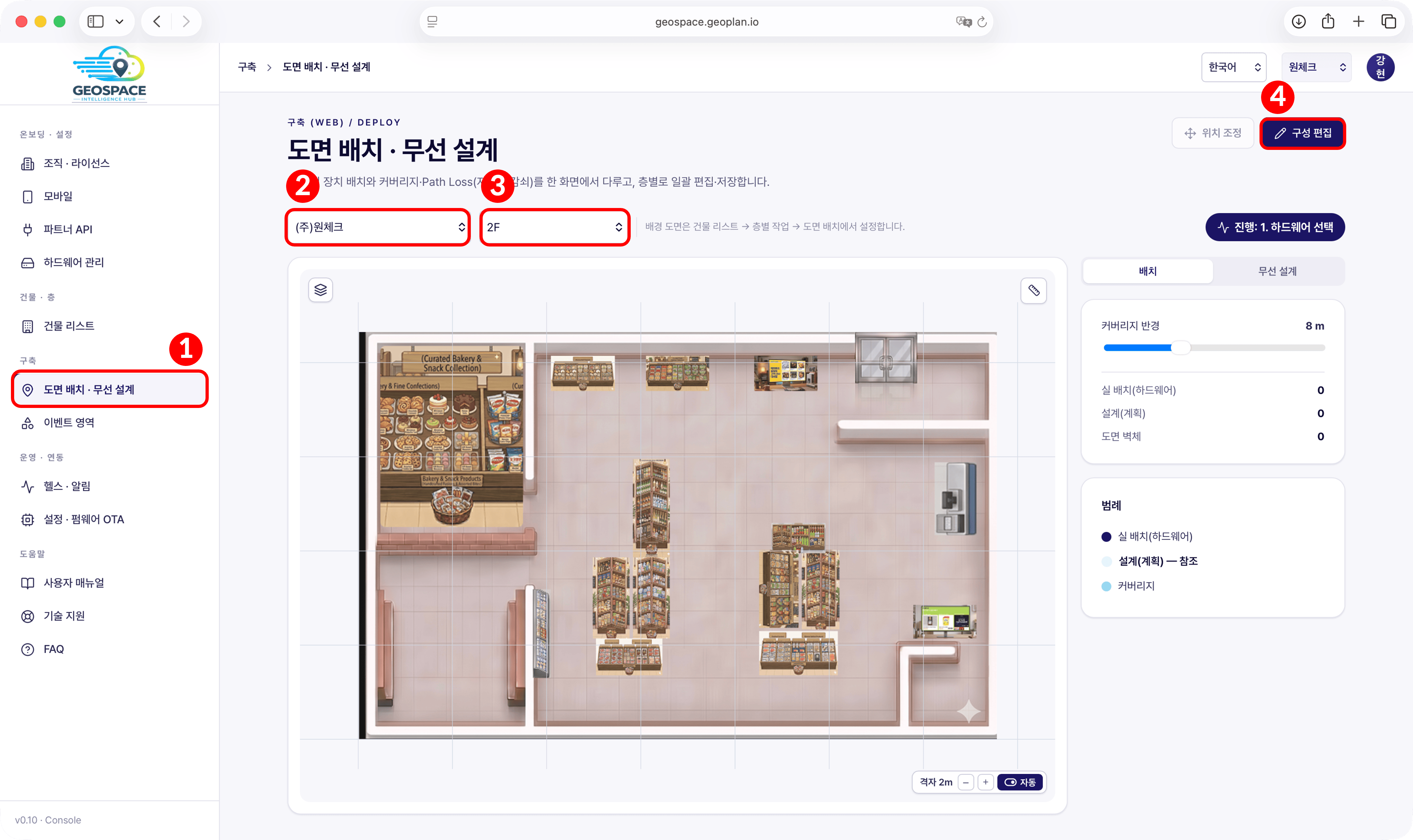
- To register and place locators on this floor · Use [Edit Configuration] at the top right of the screen. Proceed in the order Hardware → Position Placement → Cluster. (All registered locators must be powered on with Wi-Fi connected. The hardware selection list and the cluster connection list are based on each locator’s power and connection state, so before you start, confirm on-site that the LEDs on all 4 locators are lit and the bottom LED is blue (server connected).)
- To fix only locator coordinates on a floor that is already ‘Deployment Complete’ · Use [Position Adjustment] at the top right. See 4) Adjusting Coordinates Only After Deployment Complete.
If you did not register a plan
Floors without a plan from 3. Space Registration show a blank screen instead of a plan on the placement screen. The procedure is the same as with a plan: place the locators anywhere on the blank screen, then enter the measured X, Y, and Z values directly in the ‘Placed’ list. Set the reference locator to (0, 0) and enter the values so that the coordinate differences between locators match the measured distances.
Floors without a plan from 3. Space Registration show a blank screen instead of a plan on the placement screen. The procedure is the same as with a plan: place the locators anywhere on the blank screen, then enter the measured X, Y, and Z values directly in the ‘Placed’ list. Set the reference locator to (0, 0) and enter the values so that the coordinate differences between locators match the measured distances.
1) Hardware Selection
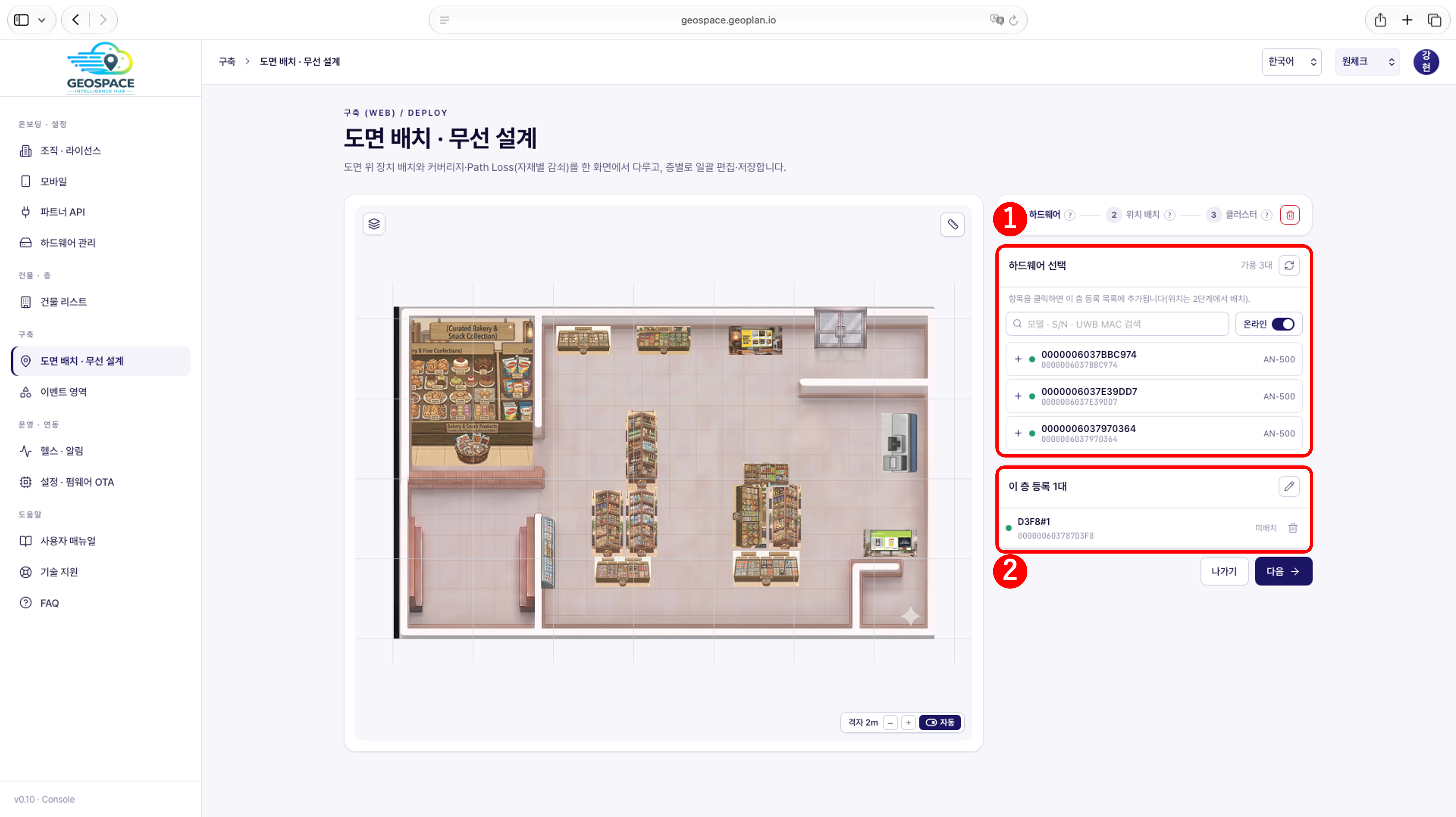
- Click a locator in the hardware selection list to add it to the ‘Registered on this floor’ list.
- Confirm the added locators appear in the ‘Registered on this floor’ list, then click [Next] to continue.
Only locators that meet all of the following appear in the list.
Locators may be excluded from the list while the ‘Online’ switch is off, so keep it on during the placement step.
- Locators with Hardware Registration complete
- Locators not yet placed on this floor’s plan
- Locators shown while the ‘Online’ switch to the right of the search box in the hardware selection list is on
Locators may be excluded from the list while the ‘Online’ switch is off, so keep it on during the placement step.
If locators are missing after resetting the configuration
Clicking the red trash icon at the right end of the step bar (1 Hardware · 2 Placement · 3 Cluster) resets this floor’s configuration and empties the list of locators registered to this floor. The reset does not remove the locators’ Hardware Registration; they remain in the [Hardware Management] list, which also shows which floor each locator is placed on. Do not provision them again thinking they are gone. Click the locators in the hardware selection list to add them to this floor again.
Clicking the red trash icon at the right end of the step bar (1 Hardware · 2 Placement · 3 Cluster) resets this floor’s configuration and empties the list of locators registered to this floor. The reset does not remove the locators’ Hardware Registration; they remain in the [Hardware Management] list, which also shows which floor each locator is placed on. Do not provision them again thinking they are gone. Click the locators in the hardware selection list to add them to this floor again.
2) Position Placement
Re-check the space dimensions, the installation position measured on-site for each locator,
and the plan orientation from 1. Pre-Installation Preparation.
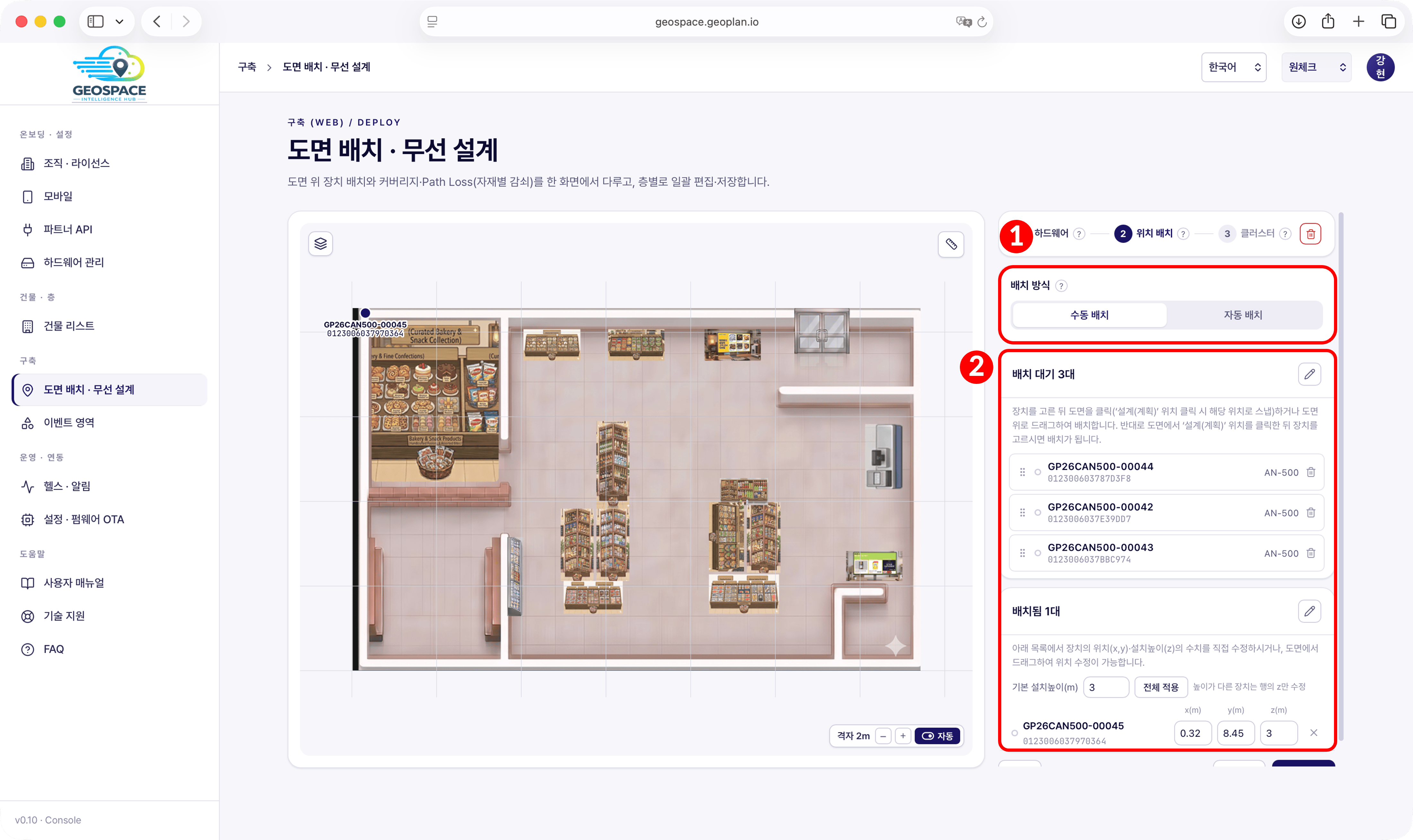
- Automatic placement is still in preparation; do not use it.
- Following the reference direction set during pre-installation preparation, the bottom-left corner becomes the coordinate reference point (conceptually 0, 0).
- X increases to the right and Y increases toward the ‘top edge’, so all coordinates inside the space should be positive.
- Placing locators at the plan’s corners is not the point in itself. What matters is entering the measured distances between locators as coordinates from the reference point, and placing them so the result matches the actual installation spots on the plan.
- If, after adjusting the coordinates to the measured values, the locator positions shown on the plan are visibly off from the actual installation spots, the plan scale is wrong. In that case, go back to 3. Space Registration, register an accurate plan, and redo the two-point scale setting.
Offset
On-screen coordinates are read against the registered plan image, not the actual space. So if the plan shows more than the exact space, including wall thickness or margins, placing against the actual space may show the reference corner as (0.4, 0.25) rather than (0, 0). The difference between the conceptual reference point and the plan coordinates is called the offset. What matters is that the distances between locator coordinates match the actual measured distances.
On-screen coordinates are read against the registered plan image, not the actual space. So if the plan shows more than the exact space, including wall thickness or margins, placing against the actual space may show the reference corner as (0.4, 0.25) rather than (0, 0). The difference between the conceptual reference point and the plan coordinates is called the offset. What matters is that the distances between locator coordinates match the actual measured distances.
Coordinate entry example
For a 10 m × 10 m space, 3 m high, with the reference point at the bottom left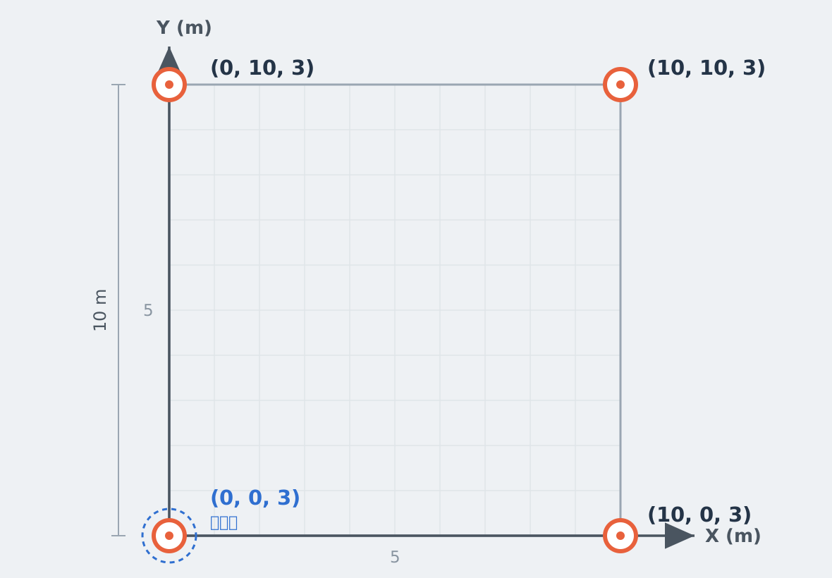
For a 10 m × 10 m space, 3 m high, with the reference point at the bottom left
Click the pencil icon at the top right of the list to rename locators placed on the plan.
The default is the S/N (e.g.,
GP26CAN500-00043); renaming to something that identifies the
installation spot makes later coordinate checks easier.- The name applies only to this floor’s plan placement; the device record in Hardware Management is unchanged.
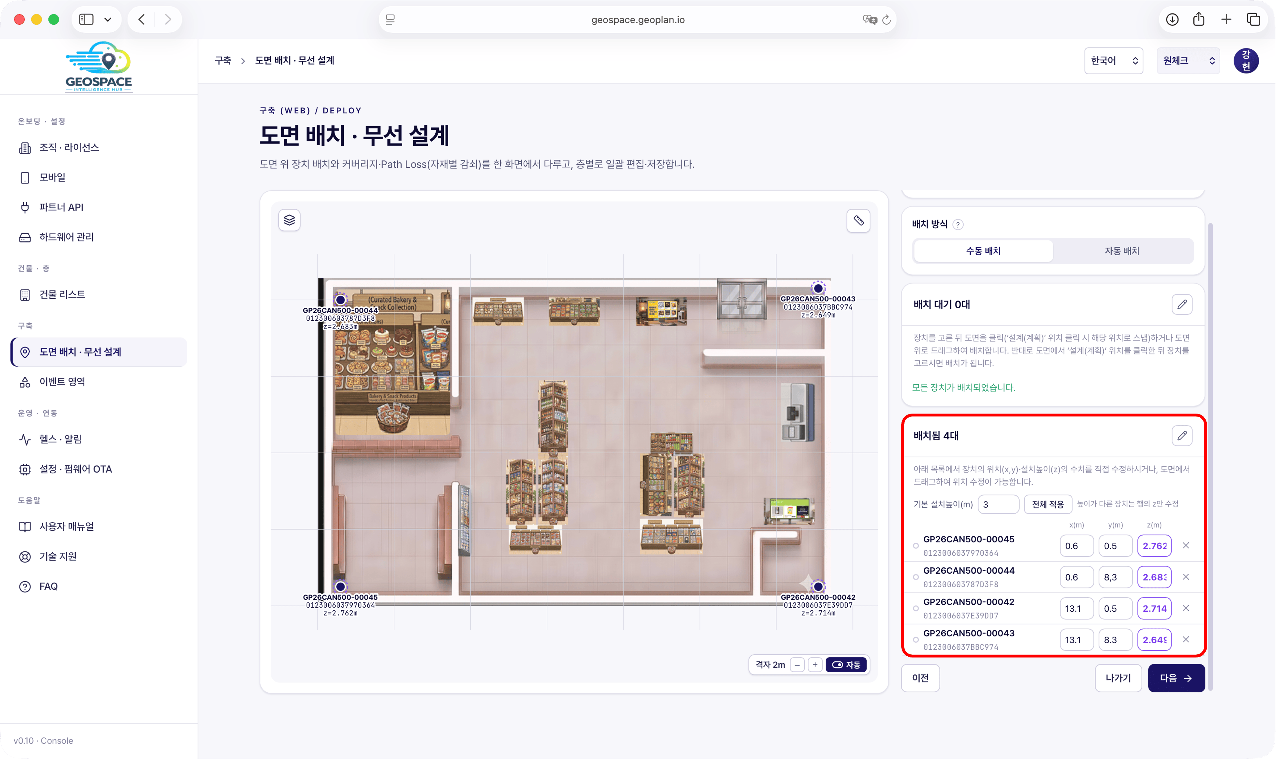
- If some locators are at a different height, edit only the z (m) value in those rows.
- The image above shows an example where each locator’s height differed slightly, so the z values were edited individually.
You can also change the plan or the reference direction you set initially. For example, you could rotate
90° counterclockwise so the former right wall becomes the ‘top edge’. In that case, replace the plan image
and re-set the reference point (0, 0) to match the new reference direction, which means redoing all the steps above.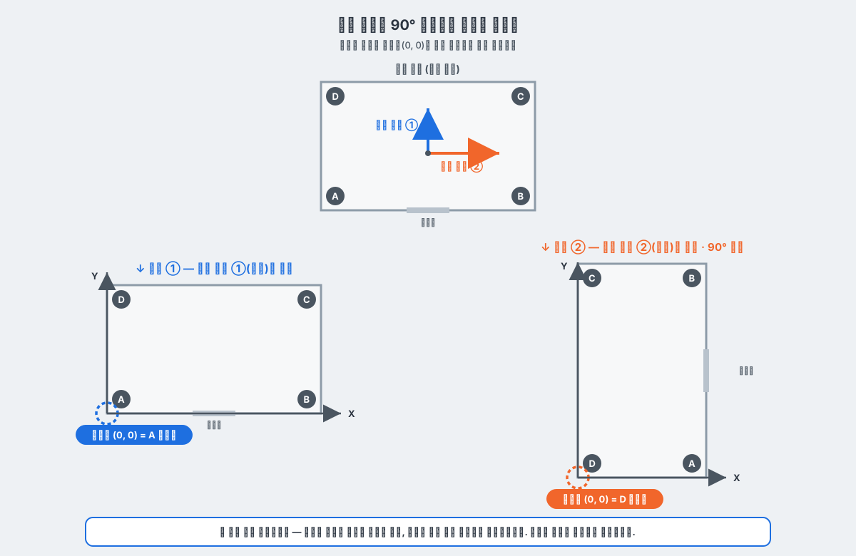
3) Cluster
Before you start
All placed locators must be connected. Only connected locators are registered in the cluster, so locators shown in gray (disconnected) on screen are left out. Check power and the Wi-Fi connection, and proceed once the bottom LED is blue.
All placed locators must be connected. Only connected locators are registered in the cluster, so locators shown in gray (disconnected) on screen are left out. Check power and the Wi-Fi connection, and proceed once the bottom LED is blue.
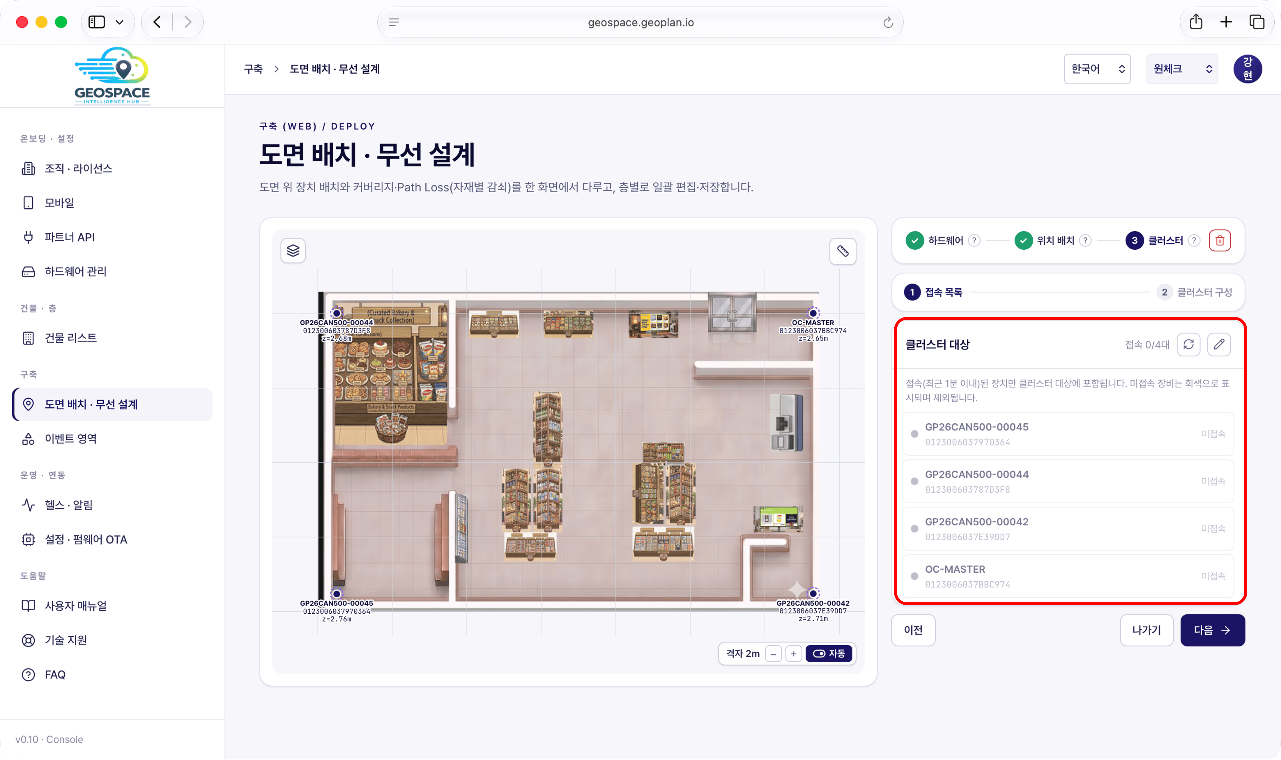
- Confirm every locator placed on this floor appears in the list, and check each locator’s power on-site.
- A notice at the top of the list reads: “Only devices connected within the last minute are included in the cluster. Disconnected devices are shown in gray and excluded.”
- If any locator shows as disconnected (gray), check its power and Wi-Fi connection and get it connected before proceeding. If you proceed with it disconnected, that locator is left out of the cluster and is not used for positioning.
- Click [Next] to move to cluster configuration.
The master locator and session ID values are provided separately, by email or otherwise, when the service is delivered.
Do not choose them yourself; enter the values you were given.
If you have not received them, contact support@ones1ght.com.
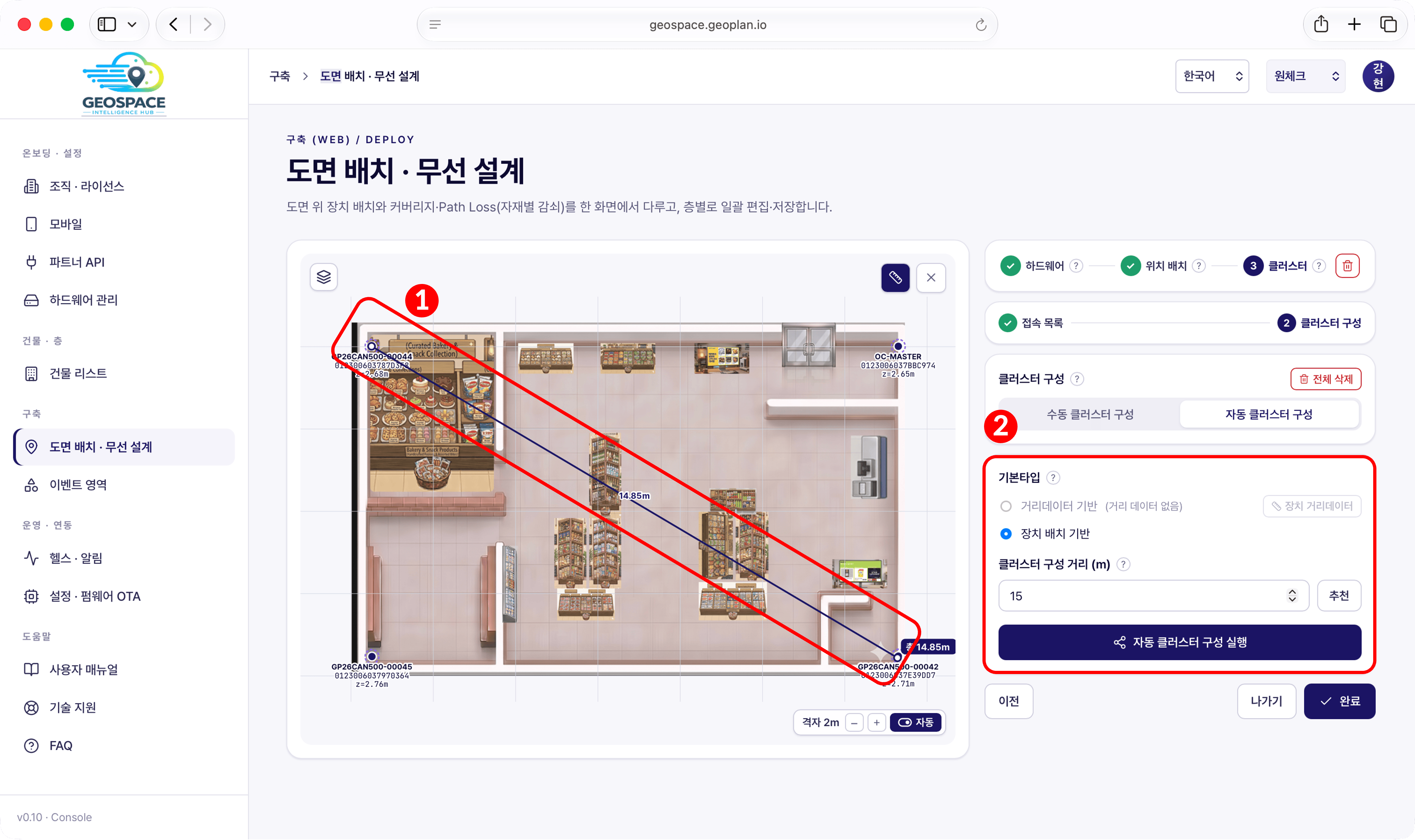
[Distance Data Based] under Base type is still in preparation; do not use it.
The steps in this document are written for [Device Placement Based].
- Clicking [Recommend] fills in a value with margin automatically.
Cluster configuration distance
The value used to group the placed locators into one cluster. Locators within the set distance are grouped into one cluster. To group 4 locators into one cluster, base the value on the distance between the two farthest locators (the diagonal), and enter slightly more than the measured distance so every locator is safely included.
The value used to group the placed locators into one cluster. Locators within the set distance are grouped into one cluster. To group 4 locators into one cluster, base the value on the distance between the two farthest locators (the diagonal), and enter slightly more than the measured distance so every locator is safely included.
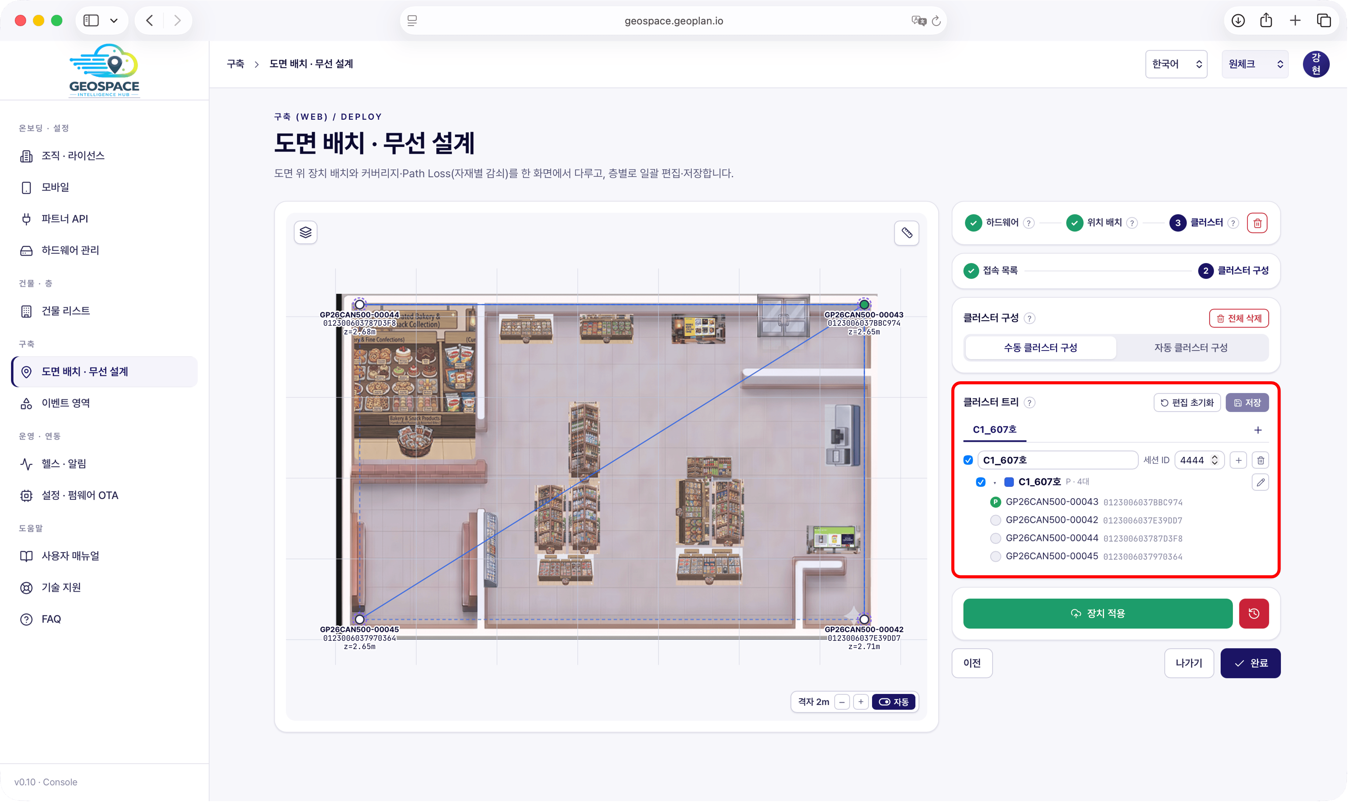
- Selecting a locator in the list marks it with a P, designating it as the master locator.
- Only one master locator can be set per cluster.
(3) Apply
Click [Apply to Devices] to push the settings to the locators. If there are unsaved changes, you are prompted to save first.
- If a disconnected-locator warning appears, that locator is left out of the cluster. Check its power and Wi-Fi connection, get it connected, then apply again.
- After applying, click [Done].
- Whether positioning actually works is confirmed in 8. Verification.
For the first apply, registration is only complete once the status is ‘Deployment Complete’.
If it stays at ‘Not Applied’ or ‘Configuration check required’, check power and the Wi-Fi connection and apply again.
Whether positioning actually works is confirmed in 8. Verification.
If you changed locators after applying the cluster
Applying the cluster registers with the server that “these locators are the positioning area of this space”. Once the status is ‘Deployment Complete’, positioning keeps working afterwards even if Wi-Fi drops or the LED blinks. However, if the locator configuration changes, you must register again.
Applying the cluster registers with the server that “these locators are the positioning area of this space”. Once the status is ‘Deployment Complete’, positioning keeps working afterwards even if Wi-Fi drops or the LED blinks. However, if the locator configuration changes, you must register again.
- A locator was re-registered to another space (floor)
- Another locator was placed in or swapped into this space
4) Adjusting Coordinates Only After Deployment Complete
Position adjustment is for fine-tuning only, when the cluster configuration does not change. If you added or replaced a locator or moved one to another floor,
re-apply from [Edit Configuration] → the Cluster tab, as described in ‘If you changed locators after applying the cluster’ under 3) Cluster.
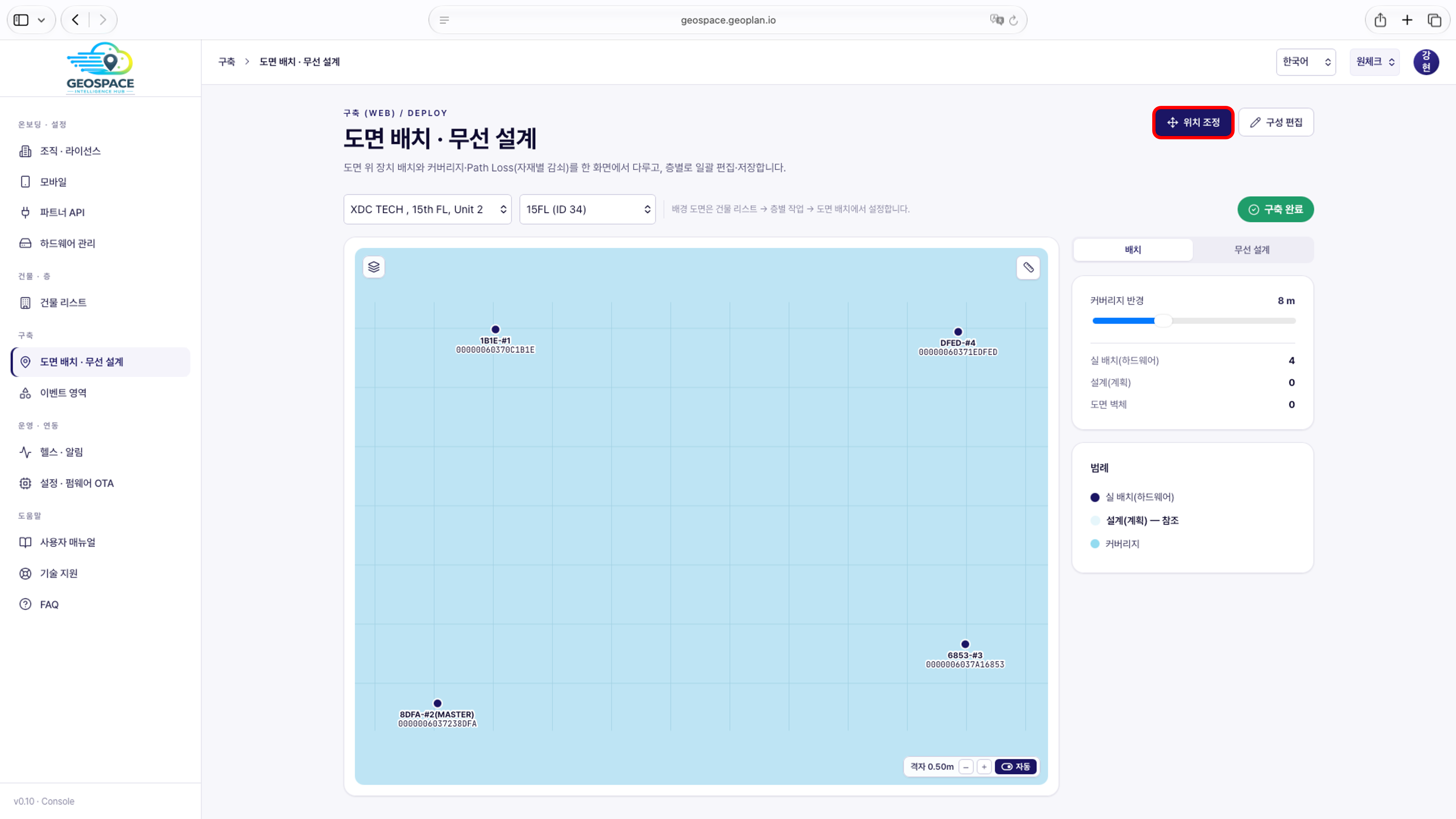
- In [Plan Placement · Wireless Design], select the building and floor and click [Position Adjustment] at the top right of the screen. The right panel switches to ‘Position Adjustment Mode · Fine-tuning only’.
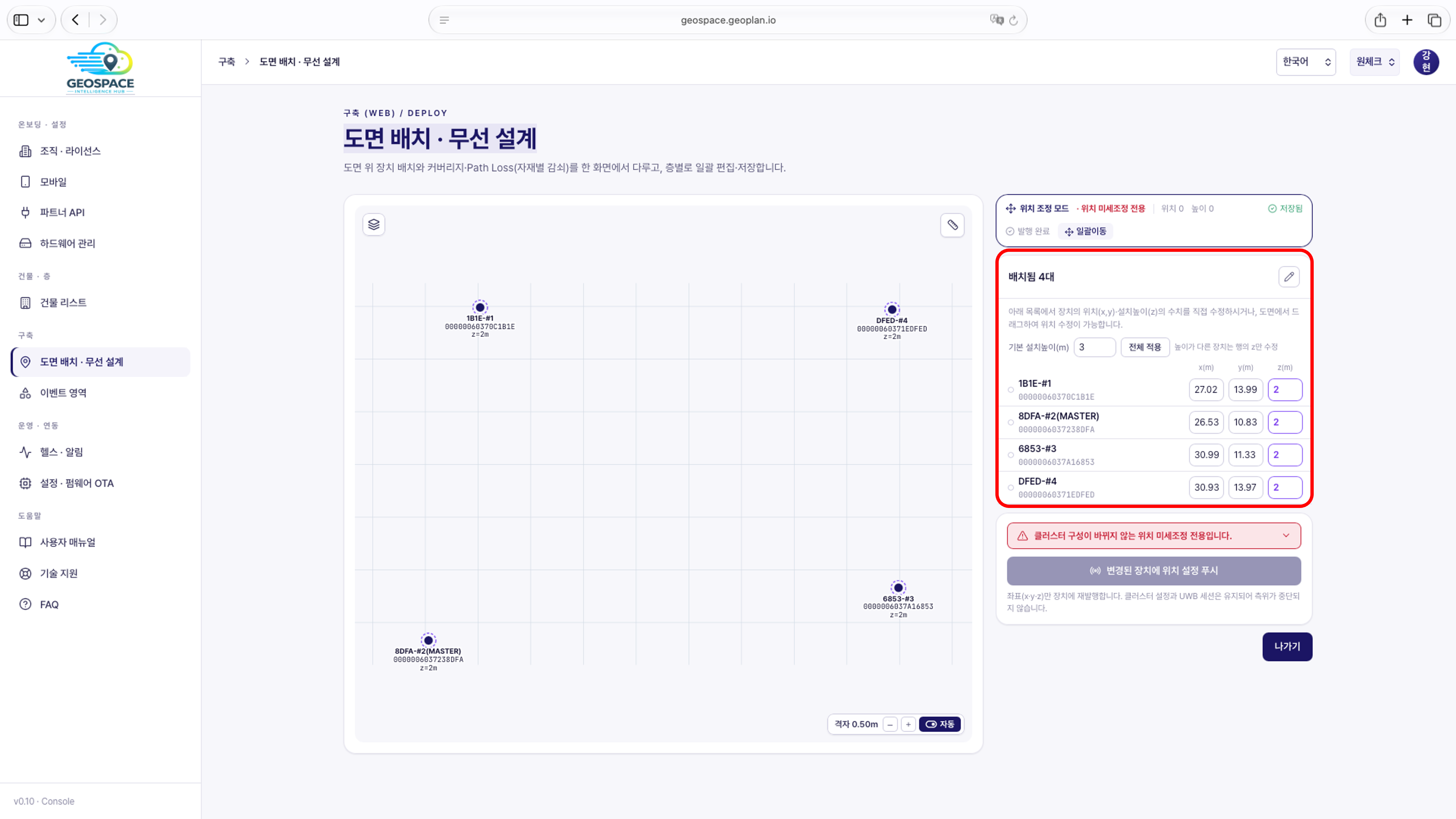
- In the ‘Placed’ list, edit each locator’s x (m) · y (m) · z (m) values directly, or drag the locator on the plan. Default installation height (m) and [Apply to All] work the same way. Changes are saved as soon as you make them (‘Saved’ appears at the top of the panel).
- If the locators are connected to Wi-Fi (bottom LED blue), click [Push Position Settings to Changed Devices] at the bottom of the panel to send the coordinates (x · y · z) to the devices as well. The button is disabled when there are no changes.
If a locator’s Wi-Fi is disconnected
The push is delivered over the locator’s Wi-Fi connection, so it does not work while the locator is disconnected. The coordinates are already saved in step 2, so you can finish with [Exit] without pushing.
The push is delivered over the locator’s Wi-Fi connection, so it does not work while the locator is disconnected. The coordinates are already saved in step 2, so you can finish with [Exit] without pushing.
- Click [Exit] to leave adjustment mode.
Checklist
Once all items below are confirmed, you can move on to the next step.