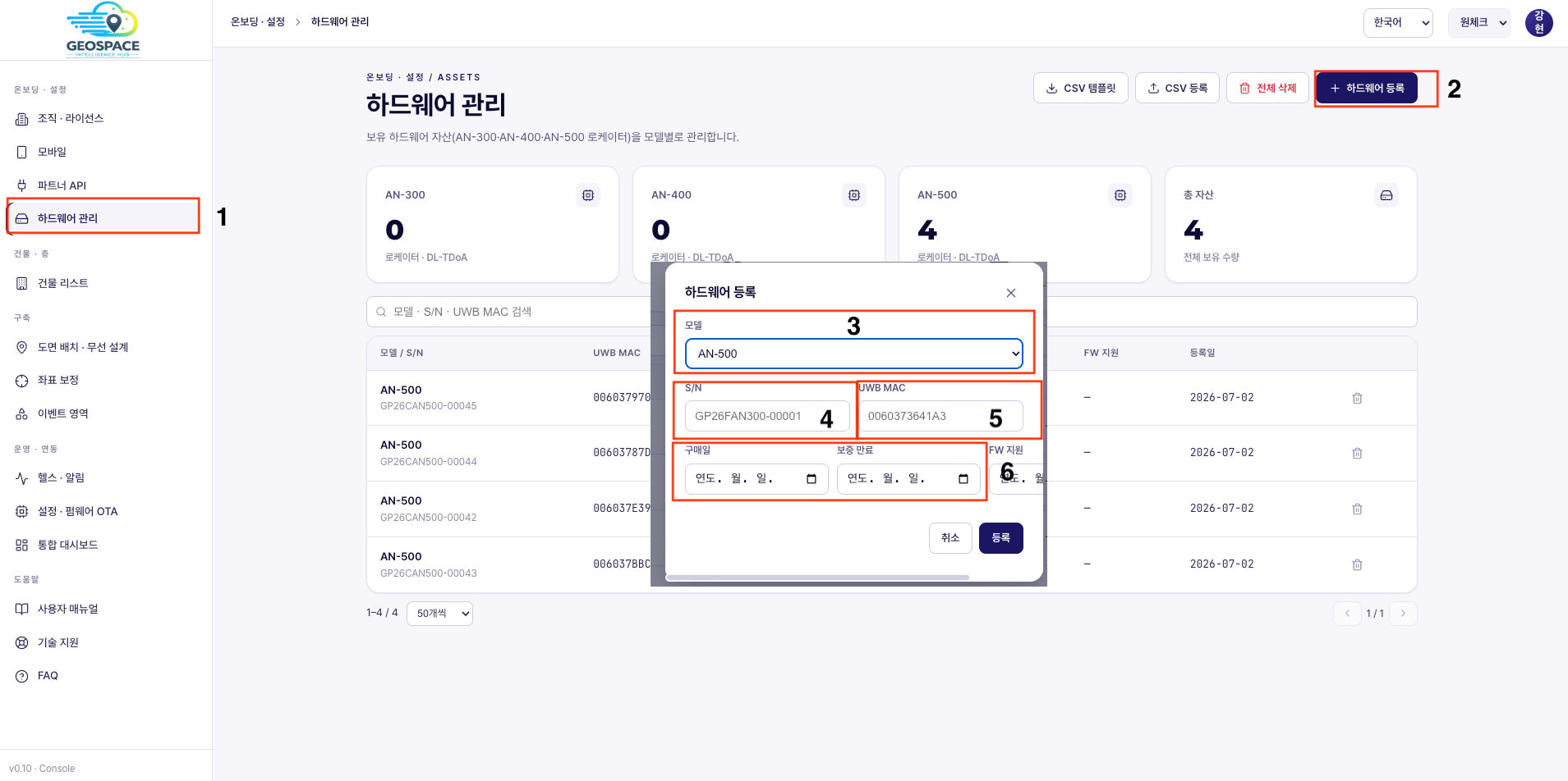
Register UWB locators (anchors) in GeoSpace, install them on site and measure their coordinates, then place and save them on the floor plan.
This page covers preparation in GeoSpace, our positioning infrastructure partner. Your spaces (buildings, floors, plans) must already be set up. (See Build spaces.)
Locator setup follows three stages: register hardware → install and measure on site → place on the plan.
Install the units at their planned positions, set an origin, and measure each anchor’s coordinates.What you need
Item
Notes
4 or more AN-500 anchors
Based on a rectangular layout surrounding the detection area
Power for each anchor
Provide power at every mounting position (an unpowered anchor takes no part in positioning)
Tape measure or laser distance meter
For measuring coordinates (X, Y, Z) from the origin
Step ladder
Needed because the recommended mounting height is 2 m or more
Avoid mounting on metal surfaces such as steel, iron, or aluminum. Radio interference can reduce positioning accuracy.
1
Mount the anchors
Anchors are typically mounted on walls. A height of 2.4 – 3 m is recommended, and
closer to 3 m is better (2 m minimum). Connect power at each position.Note: the hardware itself only tells you whether power is on. Whether positioning actually works is verified with the demo app after plan placement and cluster setup are complete (see “Next steps” below).
2
Set the origin (0, 0)
Before choosing an origin, measure the overall width and depth of the site. Place the origin wherever it is easiest to measure from.
3
Measure each anchor (X, Y, Z)
Measure each anchor’s physical position relative to the origin (0, 0, 0). 1 m in the real world = 1 coordinate unit (a 1:1 mapping).
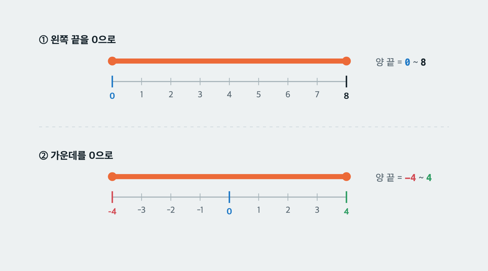
Coordinates work just like a tape measure. Where you place the zero mark changes the numbers at each end, but the length of what you measured never changes. Coordinate systems behave the same way — wherever you put the origin (0,0), the room and the anchors stay put and only the numbers change.
Same wall, different zero position: the end numbers change, the length (8) does not
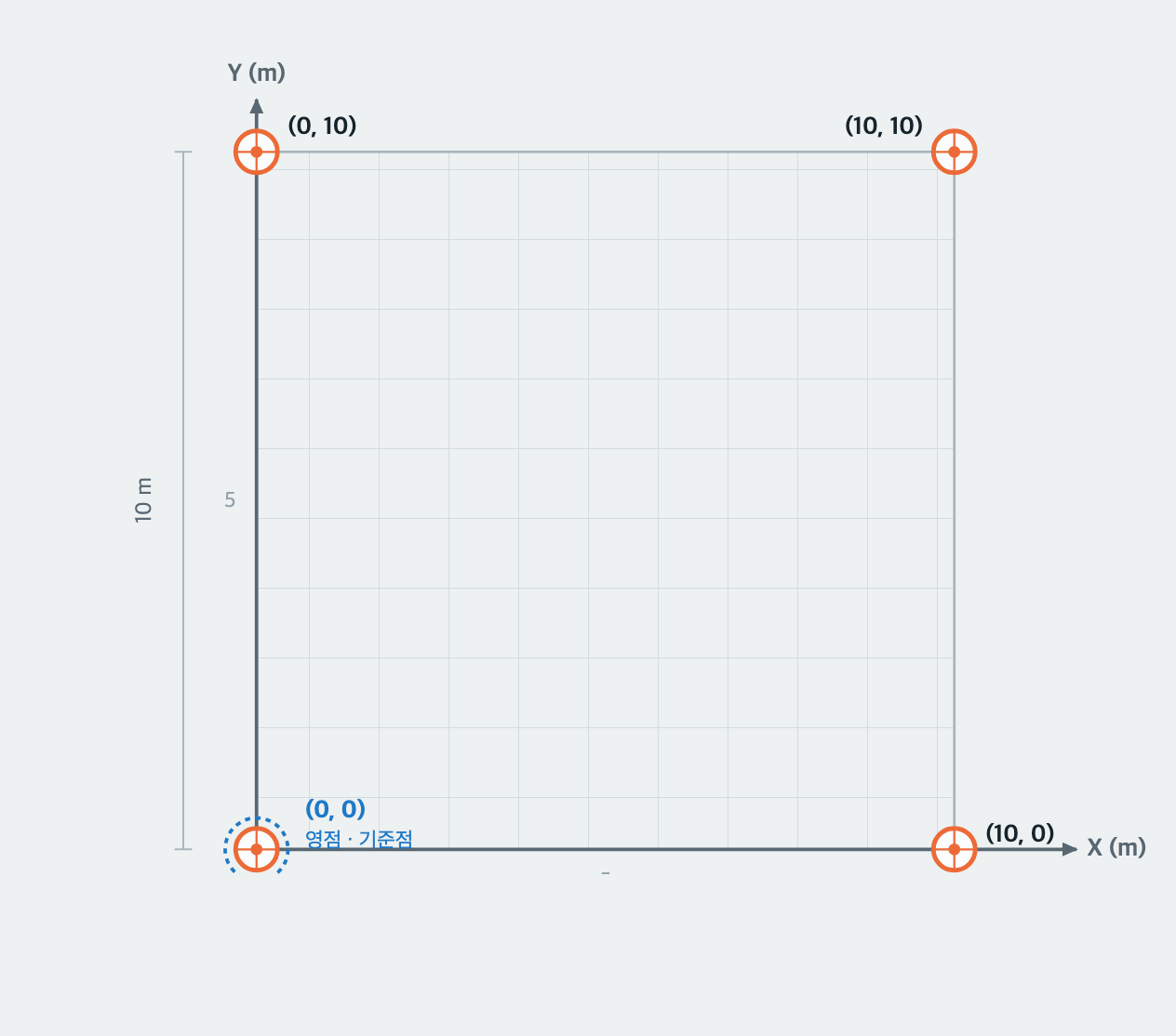
Example — for anchors at the four corners of a 10 m × 10 m space, the values you enter depend on where the origin is.
Use the bottom-left corner as the origin (0,0). All coordinates are then positive, which avoids sign mistakes when entering values.
Bottom-left corner as origin (all positive)
Bottom-left as origin. Each anchor's coordinates = (distance right, distance up)
Anchor position
X
Y
Z
Bottom left (origin)
0
0
2.4
Bottom right
10
0
2.4
Top left
0
10
2.4
Top right
10
10
2.4
Z is the mounting height from the floor (for example 2.4 m).
Place your measured locators on the plan in the console, in three stages: select hardware → place → cluster.
1
Open plan placement / RF design
In the Plan placement · RF design menu, choose the building and floor, then press [Edit].
2
Stage 1 · Select hardware
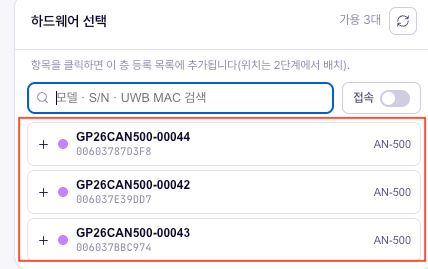
Choose anchors from the list of units not yet placed on the plan. Already-placed anchors don’t appear.
Stage 1 · Select hardware
3
Stage 2 · Place
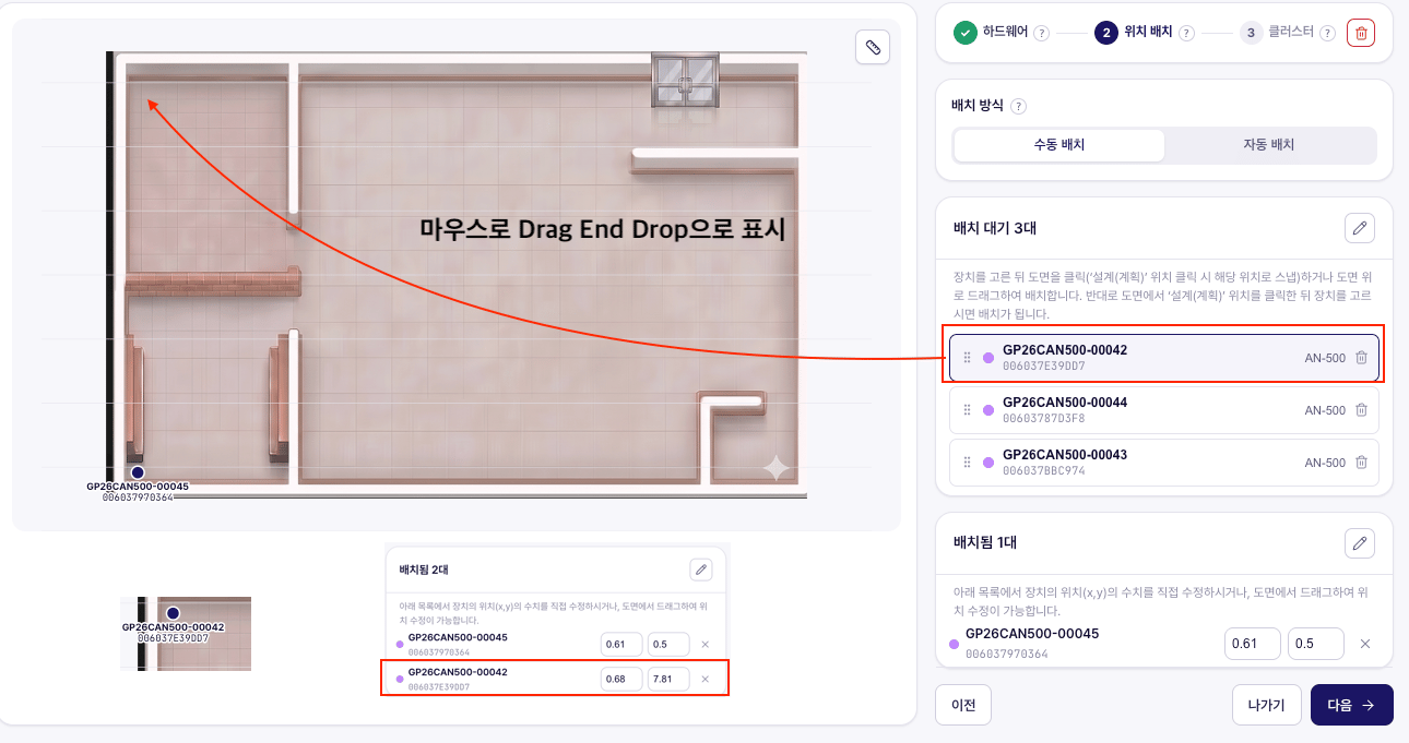
Drag each unit roughly into place on the plan, then in the “Placed” list
enter the final coordinates (x, y) numerically using your on-site measurements.
Dragging alone leaves the eyeball error in place.
(The placement screen takes X and Y only — record the Z you measured separately.)
Stage 2 · Place (drag and drop)
Use at least 4 anchors, arranged as a rectangle surrounding the detection area. Surrounding the subject from four corners keeps positioning stable. Clustering anchors on one side, or placing them close to a straight line, increases positional error.Example — Japan site (conference room), measured approx. 5.6 × 11.3 m: four anchors placed
at the corners of the detection area, enclosing the whole space.
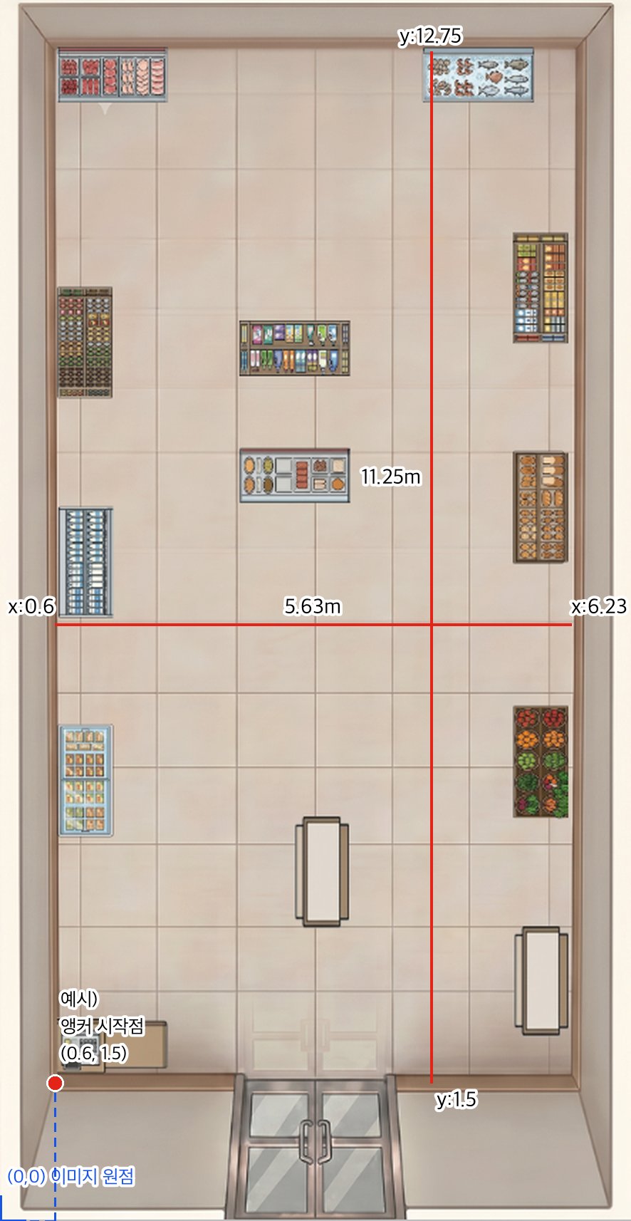
The coordinate origin is the (0, 0) of the uploaded plan image as a whole — not the corner of the room.
If the image includes walls or margins, you must add that offset to your values, and the
practical reference on the plan is the bottom-left anchor’s starting point.If you measured from a room-based origin in 2. Install on site and measure,
add the room corner’s image offset to each coordinate when entering it.
For example, if the room’s bottom-left corner sits (0.6, 1.5) from the image origin, an anchor measured
at (0, 0) is entered as (0.6, 1.5), and one measured at (5.63, 0) as (6.23, 1.5).In the example below, the bottom-left anchor is the starting point at (0.6, 1.5), with the other
three forming a rectangle 5.63 m wide and 11.25 m deep.
Example — Japan site (conference room): anchor starting point (0.6, 1.5) referenced from the wall line
Current demo site layouts — the actual values registered in the “Placed” list. Use this shape
(a rectangle at the four corners) as your reference when setting up a new site.Japan site (Akasaka 35 Kowa Building · conference room, portrait 5.63 × 11.27 m)
Unit
UWB MAC (last 4)
X
Y
Position
GP26CAN500-00002
D8C2
0.6
1.5
Bottom left (start)
GP26CAN500-00001
C83F
6.23
1.5
Bottom right
GP26CAN500-00004
C357
0.6
12.77
Top left
GP26CAN500-00003
D802
6.23
12.77
Top right
Korea site (Geumjeong Station skv1 · Room 607, landscape approx. 12.4 × 7.3 m)
Unit
UWB MAC (last 4)
X
Y
Position
GP26CAN500-00045
0364
0.61
0.5
Bottom left
GP26CAN500-00042
9DD7
12.96
0.59
Bottom right
GP26CAN500-00044
D3F8
0.59
7.8
Top left
GP26CAN500-00043
C974
12.96
7.79
Top right
Using GeoSpace Intelligence requires uploading a background plan (the floor plan image).
You upload it during Build spaces. We recommend preparing the image first
in a tool such as Flow Layout or Figma, drawing in dimensions and reference lines — seeing the origin
and starting point directly on the plan reduces coordinate entry mistakes.
4
Stage 3 · Cluster (support required)
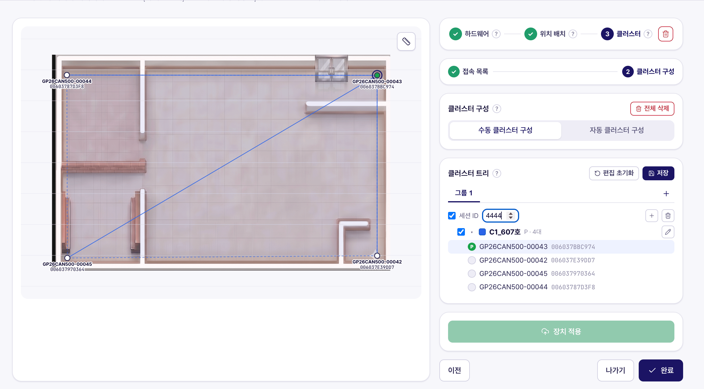
Choose the master anchor, enter the session ID, then [Save] → [Apply to devices] → [Done].
Do not choose the master anchor or session ID yourself — OneS1ght provides these values separately.
If you haven’t received them, contact us using the address below.
Stage 3 · Cluster (master anchor and session ID)
The master anchor and session ID values are provided separately by OneS1ght when you onboard. Don’t assign them yourself — enter the values you were given. If you haven’t received them, contact onesight-support@onecheck.co.kr.
Register the partner key in the OneS1ght console to enable the integration.
Space management (areas & zones)
Edit zones and points on the connected plan.
Verify positioning with the mobile demo
Once installation and placement are done, build the demo app and check that positioning (the red dot)
works on site — the most reliable way to verify your installation.