> ## Documentation Index
> Fetch the complete documentation index at: https://docs.ones1ght.com/llms.txt
> Use this file to discover all available pages before exploring further.
# 5. Floor Plan Placement · Cluster
> How to enter the anchor coordinates you measured on site into the GeoSpace floor plan, then build and apply a cluster to turn positioning on.
**Where you work —** 🖥️ GeoSpace screen
[4. Anchor installation · coordinate measurement](/en/geospace/install) must be finished, with four coordinate pairs recorded.
Once this step is done, the anchors start emitting positioning signals for real.
Work in this order: **floor plan placement → cluster**.
(Hardware registration was already completed in [step 4](/en/geospace/install#1-hardware-registration).)
## 1. Floor plan placement
Enter the coordinates you measured onto the floor plan.
Follow the numbers in the image below.
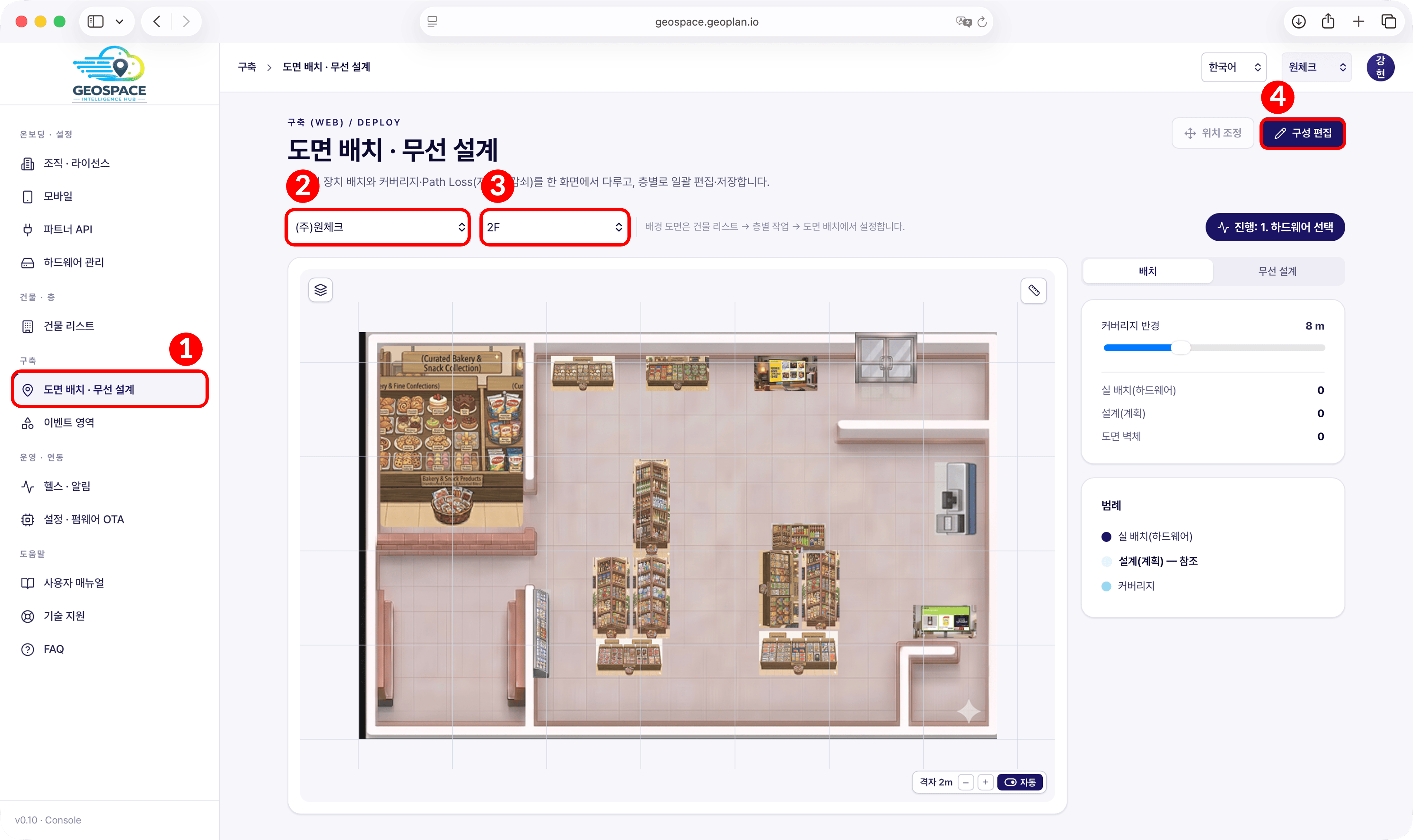 1. In the sidebar, go to **Deployment → Floor Plan Placement · Wireless Design**.
2. Select the building.
3. Select the floor.
4. Click **\[Edit]** at the top right.
Clicking Edit opens a three-step wizard on the right: **Hardware → Placement → Cluster**.
Before you click Edit, the right side of the screen shows this floor's status as numbers.
| Label | Meaning | In a 4-anchor deployment |
| ------------------------------- | --------------------------------------------------------------------------------------------------------------------- | --------------------------------- |
| **Actual placement (hardware)** | Number of anchors actually registered and placed on the floor plan | 4 is correct |
| **Design (plan)** | Number of reference points dropped inside the GCH screen — **this is not the install position you decided in step 1** | **0 is fine** — you do not use it |
| **Floor plan walls** | Number of walls drawn on the floor plan | **0 is fine** — you do not use it |
The **coverage radius** slider below is a display option that draws circles on the floor plan, so it does not affect positioning.
Everything you place in this step is **actual placement**.
1. In the sidebar, go to **Deployment → Floor Plan Placement · Wireless Design**.
2. Select the building.
3. Select the floor.
4. Click **\[Edit]** at the top right.
Clicking Edit opens a three-step wizard on the right: **Hardware → Placement → Cluster**.
Before you click Edit, the right side of the screen shows this floor's status as numbers.
| Label | Meaning | In a 4-anchor deployment |
| ------------------------------- | --------------------------------------------------------------------------------------------------------------------- | --------------------------------- |
| **Actual placement (hardware)** | Number of anchors actually registered and placed on the floor plan | 4 is correct |
| **Design (plan)** | Number of reference points dropped inside the GCH screen — **this is not the install position you decided in step 1** | **0 is fine** — you do not use it |
| **Floor plan walls** | Number of walls drawn on the floor plan | **0 is fine** — you do not use it |
The **coverage radius** slider below is a display option that draws circles on the floor plan, so it does not affect positioning.
Everything you place in this step is **actual placement**.
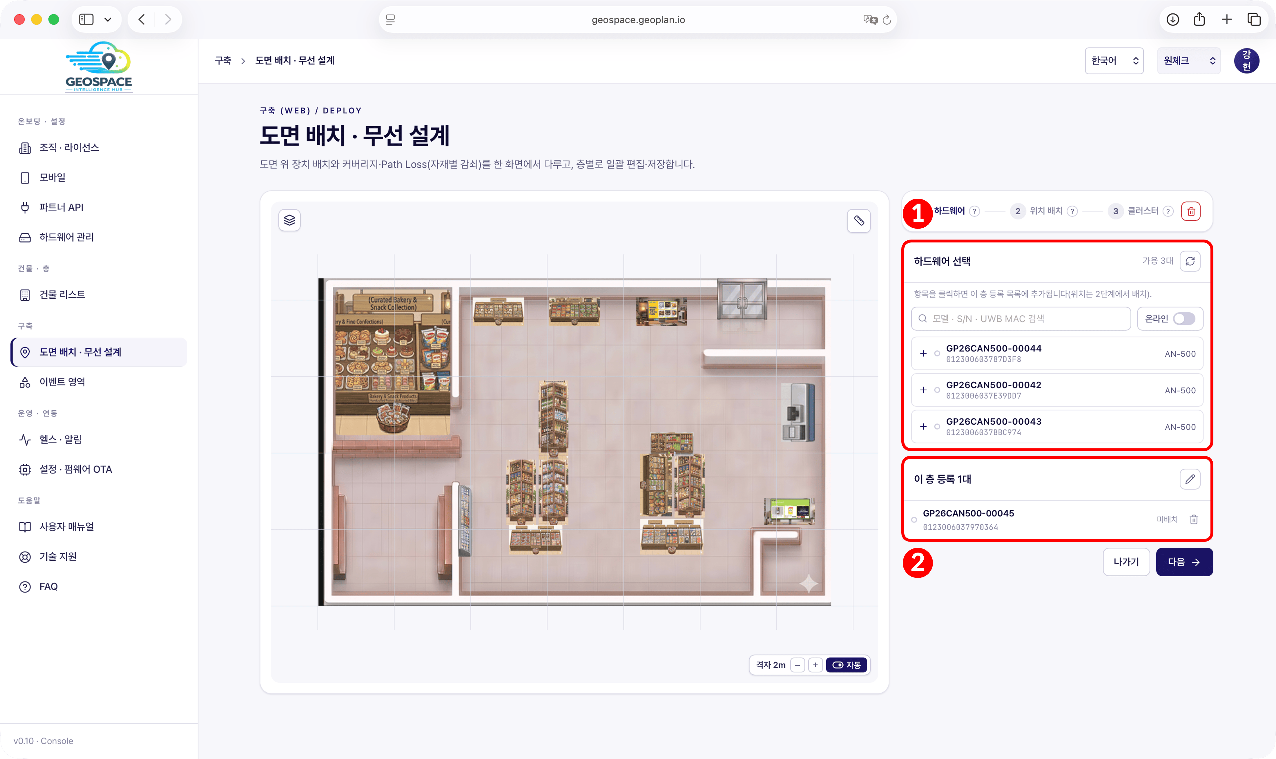 1. In the **Select hardware** list, click **\[+]** on the anchor you want to place.
2. Confirm it was added to the **Registered on this floor** list below.
**If you do not see the anchor in the list** — three conditions decide what appears.
1. The device must have completed [hardware registration](/en/geospace/install#1-hardware-registration) (step 4),
2. of those, only anchors **not yet placed on the floor plan** appear, and
3. leave the **online toggle OFF** — turning it on can make the list look empty.
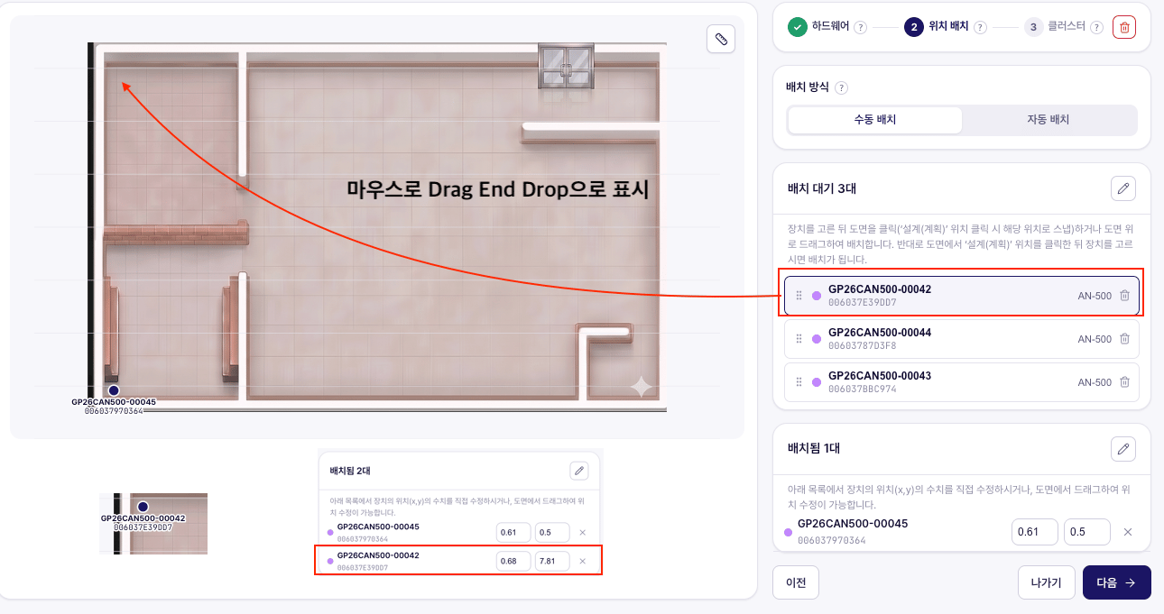
Leave the placement mode at the top of the screen on **Manual placement**.
**Drag** each device roughly onto its real install position on the floor plan, then in the 'Placed' list
**type the final coordinates (x, y) in as numbers, using the [values you measured on site](/en/geospace/install#3-setting-the-origin-and-measuring-coordinates)**.
If you stop at dragging, the eyeball error stays in the data. Once all four are entered, click **\[Next]** to move on to the cluster step.
In the coordinate fields, **the left one is X (horizontal) and the right one is Y (vertical)**, and Y **increases toward the top** of the floor plan.
(The placement screen takes X and Y only — keep the Z you measured (install height) recorded separately.)
1. In the **Select hardware** list, click **\[+]** on the anchor you want to place.
2. Confirm it was added to the **Registered on this floor** list below.
**If you do not see the anchor in the list** — three conditions decide what appears.
1. The device must have completed [hardware registration](/en/geospace/install#1-hardware-registration) (step 4),
2. of those, only anchors **not yet placed on the floor plan** appear, and
3. leave the **online toggle OFF** — turning it on can make the list look empty.
Leave the placement mode at the top of the screen on **Manual placement**.
**Drag** each device roughly onto its real install position on the floor plan, then in the 'Placed' list
**type the final coordinates (x, y) in as numbers, using the [values you measured on site](/en/geospace/install#3-setting-the-origin-and-measuring-coordinates)**.
If you stop at dragging, the eyeball error stays in the data. Once all four are entered, click **\[Next]** to move on to the cluster step.
In the coordinate fields, **the left one is X (horizontal) and the right one is Y (vertical)**, and Y **increases toward the top** of the floor plan.
(The placement screen takes X and Y only — keep the Z you measured (install height) recorded separately.)
 **The coordinates on this screen are relative to the floor plan image** — the origin (0, 0) is the bottom-left corner of the image.
If the floor plan includes wall thickness or space in front of the entrance, the corner of the room sits that far from the image origin,
and that distance is called the **offset**. Positioning still works if you ignore the offset, but
**your dot and your zones appear shifted by that distance in the app.**
**The coordinates on this screen are relative to the floor plan image** — the origin (0, 0) is the bottom-left corner of the image.
If the floor plan includes wall thickness or space in front of the entrance, the corner of the room sits that far from the image origin,
and that distance is called the **offset**. Positioning still works if you ignore the offset, but
**your dot and your zones appear shifted by that distance in the app.**
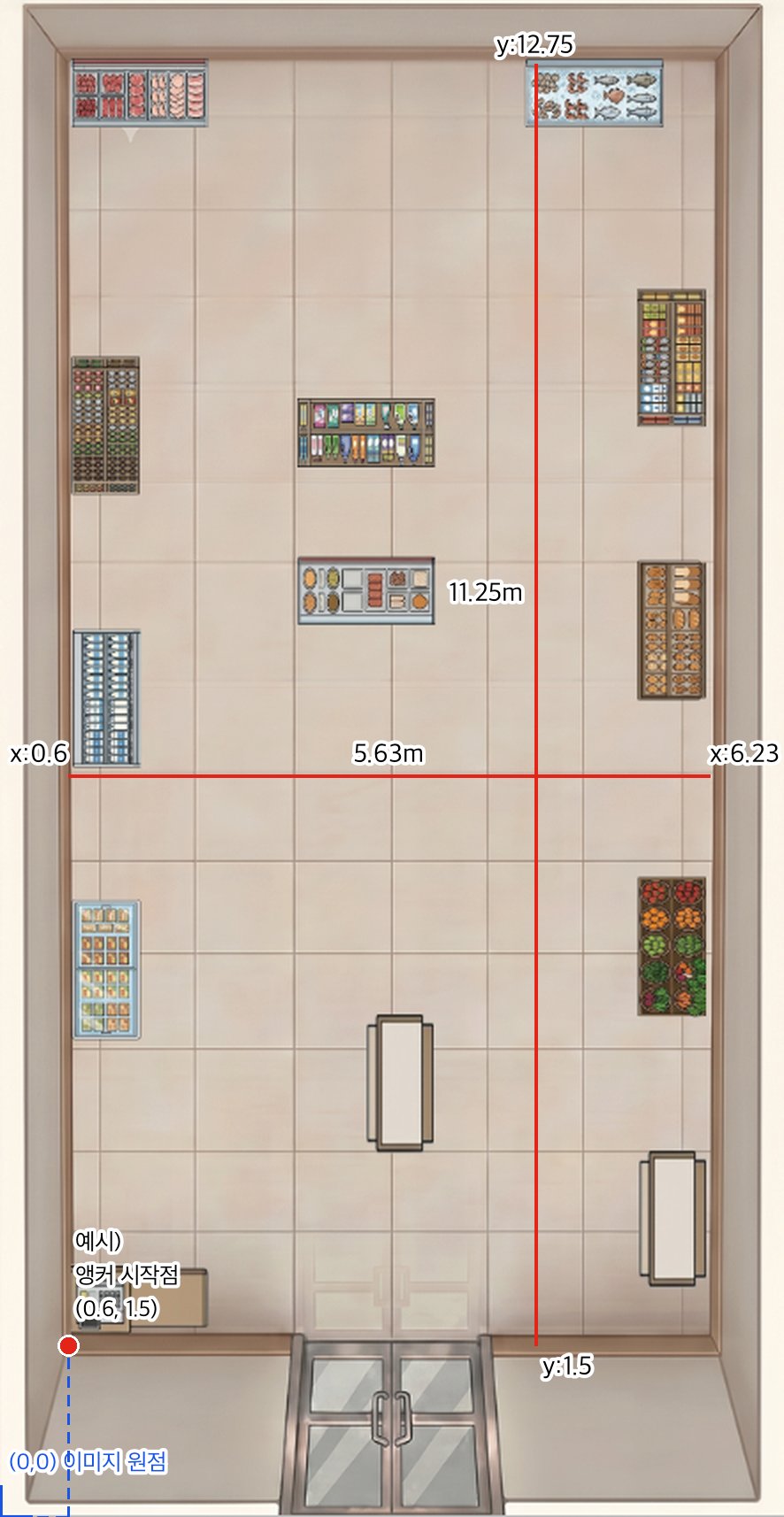 #### ① Find the offset for your site — read it off the screen, do not calculate it
1. Drag the anchor you set as the origin (0, 0) on site (bottom-left of the room) onto
**that corner on the floor plan (where the walls start)** — wall corners are visible on the plan, so you can line it up.
2. Read the coordinates shown in the 'Placed' list. **That value is your site's offset.**
#### ② What you type depends on the value you read
| Value you read | How to enter it |
| -------------------------------------- | -------------------------------------------------------------------------------------------------------------------------------------------------------------------------------------------------- |
| **Within ± 10 cm** (e.g. 0.04, 0.07) | Ignore it — enter the **measured values as they are** for all four (it falls [within measurement error](/en/geospace/install#3-setting-the-origin-and-measuring-coordinates), so it means nothing) |
| **Tens of cm or more** (e.g. 0.6, 1.5) | Enter **measured value + offset** for all four (see the table below) |
The example in the image above has a **large** offset — the floor plan image includes **the space in front of the entrance**, outside the room, which opened up a 1.5 m vertical gap.
If the plan was drawn to match the room, the offset is usually about the wall thickness (a few cm) and you can just move on.
Below is the calculation for the site in the image above (offset 0.6, 1.5). Your site has a different offset and different measurements,
so take the **method**, not the numbers.
| Measured value (room-relative) | + offset | = value to enter |
| ------------------------------ | ---------- | ----------------- |
| (0, 0) | (0.6, 1.5) | **(0.6, 1.5)** |
| (5.63, 0) | (0.6, 1.5) | **(6.23, 1.5)** |
| (0, 11.25) | (0.6, 1.5) | **(0.6, 12.75)** |
| (5.63, 11.25) | (0.6, 1.5) | **(6.23, 12.75)** |
**Demo site placement example** — these are the values actually registered in the demo site's 'Placed' list.
At a new site, take the **shape (a rectangle with an anchor at each corner), not the numbers**.
*Site 1 (portrait, 5.63 × 11.25 m)*
| Device | UWB MAC (last 4) | X | Y | Position |
| ---------------- | ---------------- | ---- | ----- | ------------------------- |
| GP26CAN500-00002 | `D8C2` | 0.6 | 1.5 | Bottom-left (start point) |
| GP26CAN500-00001 | `C83F` | 6.23 | 1.5 | Bottom-right |
| GP26CAN500-00004 | `C357` | 0.6 | 12.75 | Top-left |
| GP26CAN500-00003 | `D802` | 6.23 | 12.75 | Top-right |
*Site 2 (landscape, roughly 12.4 × 7.3 m)* — for a small landscape-shaped store, you can copy the **shape** in this table as it is.
| Device | UWB MAC (last 4) | X | Y | Position |
| ---------------- | ---------------- | ----- | ---- | ------------ |
| GP26CAN500-00045 | `0364` | 0.61 | 0.5 | Bottom-left |
| GP26CAN500-00042 | `9DD7` | 12.96 | 0.59 | Bottom-right |
| GP26CAN500-00044 | `D3F8` | 0.59 | 7.8 | Top-left |
| GP26CAN500-00043 | `C974` | 12.96 | 7.79 | Top-right |
**Writing the site survey dimensions and the entrance position onto the floor plan image as text** lets you read the origin and the offset straight off the plan,
which cuts down coordinate-entry mistakes — see [Preparation · floor plan preparation](/en/geospace/site-survey#4-floor-plan-preparation).
## 2. Cluster · apply to devices
A **cluster** is the setting that binds anchors into a single time-synchronized group. The four anchors must share a time base
before a device can compute a position, and pushing that setting down to the physical hardware is **apply to devices**.
Only once this step is done do the anchors start emitting positioning signals.
**Before you start —** check that all four anchors are powered on.
Anchors shown in grey on screen appear that way because they are not connected to the server;
if you are sure the power is on, you can carry on as is (see the apply to devices step below).
**The master anchor (initiator) and the session ID values are provided separately by OneS1ght when the service is set up.**
Do not pick them yourself — enter the values you were given. If you did not receive them,
contact `onesight-support@onecheck.co.kr`.
The cluster tab opens on the **connection list** — the connection status of the anchors you placed on this floor.
#### ① Find the offset for your site — read it off the screen, do not calculate it
1. Drag the anchor you set as the origin (0, 0) on site (bottom-left of the room) onto
**that corner on the floor plan (where the walls start)** — wall corners are visible on the plan, so you can line it up.
2. Read the coordinates shown in the 'Placed' list. **That value is your site's offset.**
#### ② What you type depends on the value you read
| Value you read | How to enter it |
| -------------------------------------- | -------------------------------------------------------------------------------------------------------------------------------------------------------------------------------------------------- |
| **Within ± 10 cm** (e.g. 0.04, 0.07) | Ignore it — enter the **measured values as they are** for all four (it falls [within measurement error](/en/geospace/install#3-setting-the-origin-and-measuring-coordinates), so it means nothing) |
| **Tens of cm or more** (e.g. 0.6, 1.5) | Enter **measured value + offset** for all four (see the table below) |
The example in the image above has a **large** offset — the floor plan image includes **the space in front of the entrance**, outside the room, which opened up a 1.5 m vertical gap.
If the plan was drawn to match the room, the offset is usually about the wall thickness (a few cm) and you can just move on.
Below is the calculation for the site in the image above (offset 0.6, 1.5). Your site has a different offset and different measurements,
so take the **method**, not the numbers.
| Measured value (room-relative) | + offset | = value to enter |
| ------------------------------ | ---------- | ----------------- |
| (0, 0) | (0.6, 1.5) | **(0.6, 1.5)** |
| (5.63, 0) | (0.6, 1.5) | **(6.23, 1.5)** |
| (0, 11.25) | (0.6, 1.5) | **(0.6, 12.75)** |
| (5.63, 11.25) | (0.6, 1.5) | **(6.23, 12.75)** |
**Demo site placement example** — these are the values actually registered in the demo site's 'Placed' list.
At a new site, take the **shape (a rectangle with an anchor at each corner), not the numbers**.
*Site 1 (portrait, 5.63 × 11.25 m)*
| Device | UWB MAC (last 4) | X | Y | Position |
| ---------------- | ---------------- | ---- | ----- | ------------------------- |
| GP26CAN500-00002 | `D8C2` | 0.6 | 1.5 | Bottom-left (start point) |
| GP26CAN500-00001 | `C83F` | 6.23 | 1.5 | Bottom-right |
| GP26CAN500-00004 | `C357` | 0.6 | 12.75 | Top-left |
| GP26CAN500-00003 | `D802` | 6.23 | 12.75 | Top-right |
*Site 2 (landscape, roughly 12.4 × 7.3 m)* — for a small landscape-shaped store, you can copy the **shape** in this table as it is.
| Device | UWB MAC (last 4) | X | Y | Position |
| ---------------- | ---------------- | ----- | ---- | ------------ |
| GP26CAN500-00045 | `0364` | 0.61 | 0.5 | Bottom-left |
| GP26CAN500-00042 | `9DD7` | 12.96 | 0.59 | Bottom-right |
| GP26CAN500-00044 | `D3F8` | 0.59 | 7.8 | Top-left |
| GP26CAN500-00043 | `C974` | 12.96 | 7.79 | Top-right |
**Writing the site survey dimensions and the entrance position onto the floor plan image as text** lets you read the origin and the offset straight off the plan,
which cuts down coordinate-entry mistakes — see [Preparation · floor plan preparation](/en/geospace/site-survey#4-floor-plan-preparation).
## 2. Cluster · apply to devices
A **cluster** is the setting that binds anchors into a single time-synchronized group. The four anchors must share a time base
before a device can compute a position, and pushing that setting down to the physical hardware is **apply to devices**.
Only once this step is done do the anchors start emitting positioning signals.
**Before you start —** check that all four anchors are powered on.
Anchors shown in grey on screen appear that way because they are not connected to the server;
if you are sure the power is on, you can carry on as is (see the apply to devices step below).
**The master anchor (initiator) and the session ID values are provided separately by OneS1ght when the service is set up.**
Do not pick them yourself — enter the values you were given. If you did not receive them,
contact `onesight-support@onecheck.co.kr`.
The cluster tab opens on the **connection list** — the connection status of the anchors you placed on this floor.
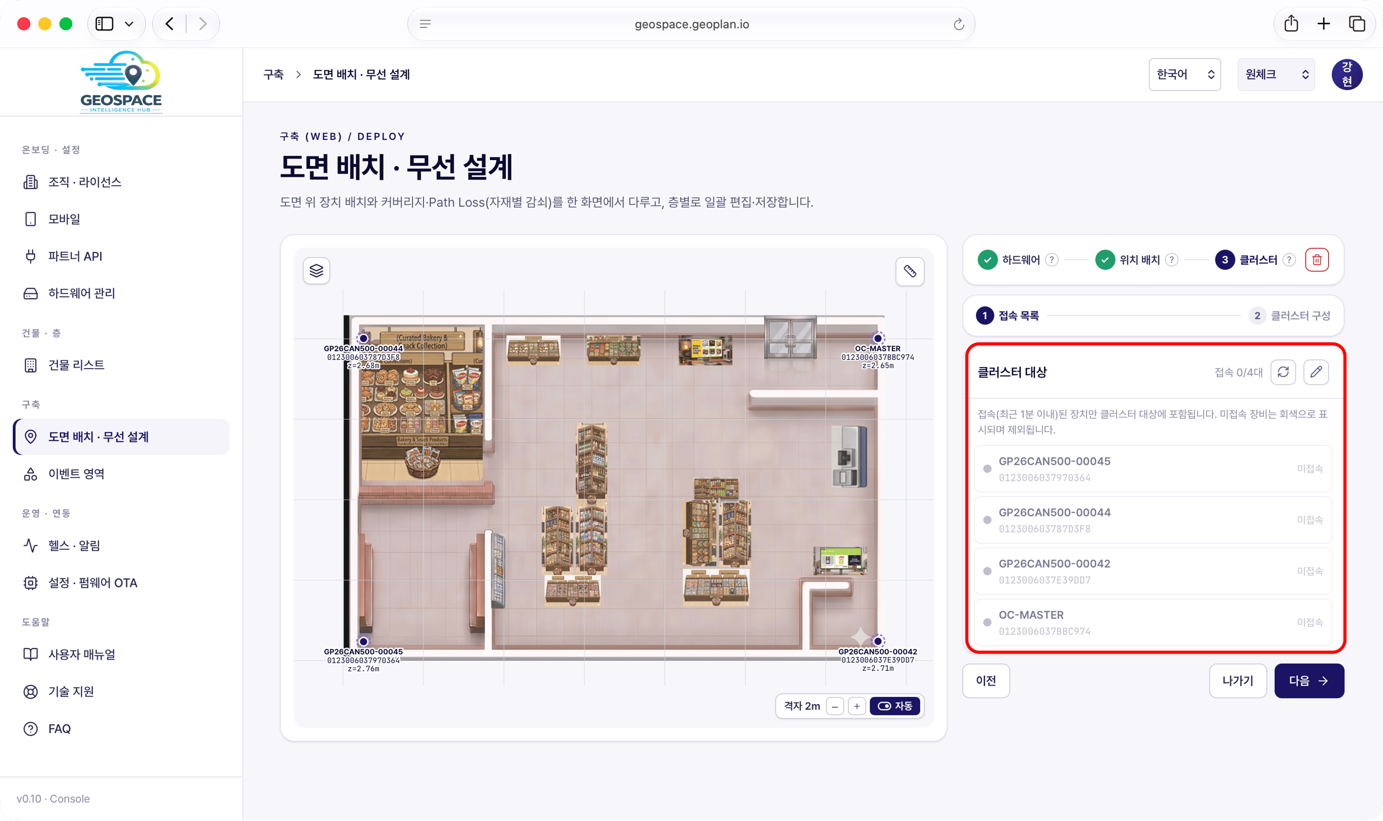 1. Check that all four are in the list and that they are powered on at the site.
The on-screen message "Only devices connected (within the last minute) are included in the cluster. Disconnected devices are shown in grey and excluded."
and the **Disconnected** label **can appear even when everything is fine**. If the LEDs on all four anchors are **on (not red)**, carry on.
2. Click **\[Next]**.
1. Check that all four are in the list and that they are powered on at the site.
The on-screen message "Only devices connected (within the last minute) are included in the cluster. Disconnected devices are shown in grey and excluded."
and the **Disconnected** label **can appear even when everything is fine**. If the LEDs on all four anchors are **on (not red)**, carry on.
2. Click **\[Next]**.
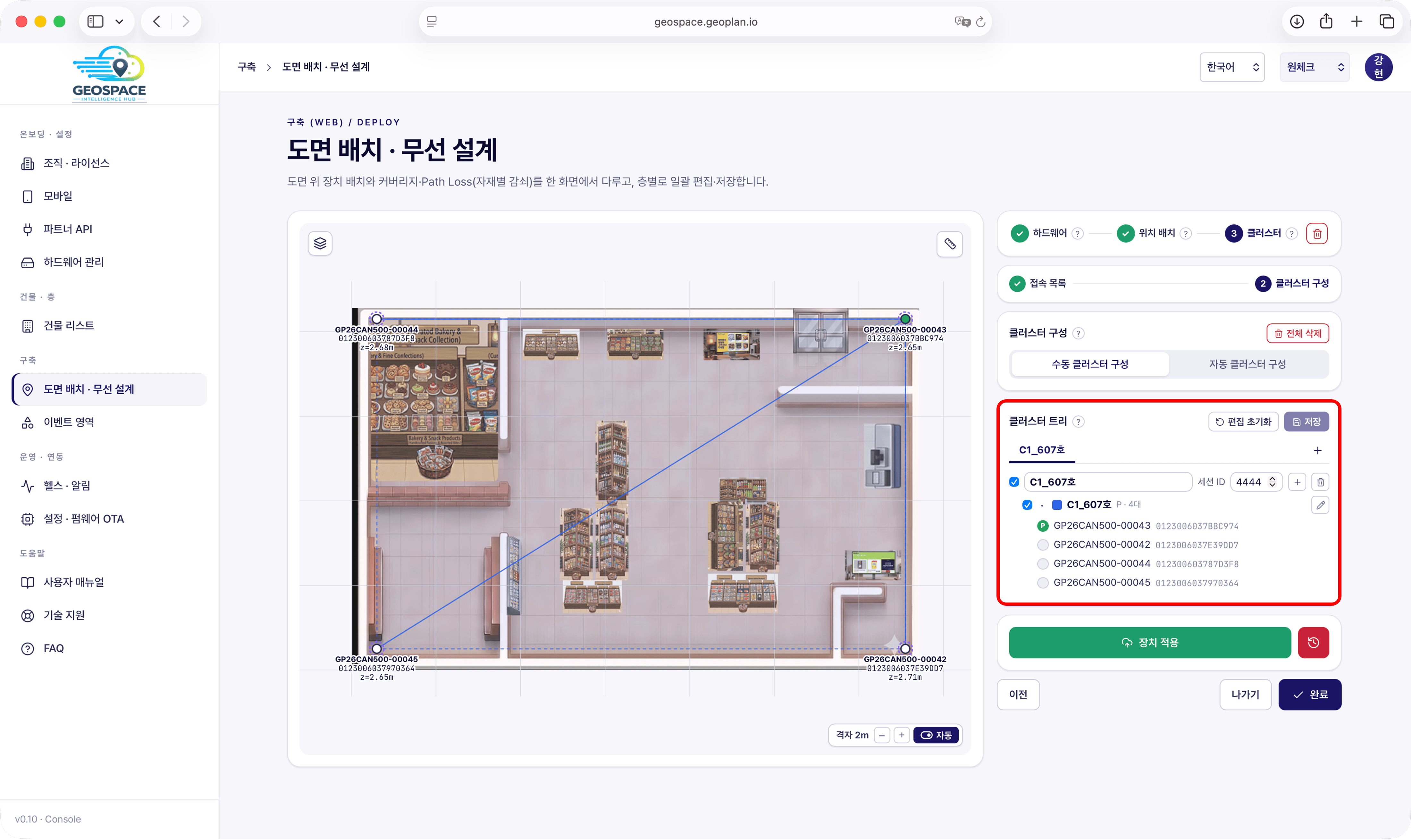 3. Click **\[+]** to create one group. One group is enough for a small four-anchor site.
4. **Session ID** — enter the value you were given into the group.
5. **Master anchor** — turn on the **P** radio button for the anchor you were told to use.
The anchor with P on runs as **INP** (master, initiator); the rest run as **RES** (responder).
6. Click **\[Save]**. If you changed something by mistake, **\[Reset edits]** takes you back to the state before saving.
7. Click **\[Apply to devices]** to publish the settings to the anchors. If you have unsaved changes, you are asked to save first.
Even if a disconnected-anchor warning appears, continue with **\[Apply to devices anyway]** and then click **\[Done]** —
whether it actually works is confirmed in [step 7, verification](/en/geospace/verify).
**Checkpoint —** if you got through **\[Apply to devices] → \[Done]** and the tree shows a **Done** badge, this step is complete.
The anchors are now emitting positioning signals — whether a position is actually fixed is confirmed in step 7.
| Status | Meaning | What to do |
| ------------------------ | ------------------------------------------------------------------------------- | -------------------------------------------------------------------------------------------------------------- |
| **Applied** (Done badge) | Publishing finished | Move to the next step |
| **Not applied** | Configuration saved, not published yet | Run \[Apply to devices] |
| **Configuration failed** | Publishing failed on some anchors — the floor shows 'Needs configuration check' | Check anchor power and connection, then **re-apply**. If it still fails, judge by actual positioning in step 7 |
For a **large site with more than eight anchors**, you need extra rules for running multiple clusters (secondary clusters, overlap) —
contact `onesight-support@onecheck.co.kr` in that case. For a small four-anchor deployment the procedure above is enough.
## Next step
Issue a partner key and connect to the OneS1ght console (SW binding).
3. Click **\[+]** to create one group. One group is enough for a small four-anchor site.
4. **Session ID** — enter the value you were given into the group.
5. **Master anchor** — turn on the **P** radio button for the anchor you were told to use.
The anchor with P on runs as **INP** (master, initiator); the rest run as **RES** (responder).
6. Click **\[Save]**. If you changed something by mistake, **\[Reset edits]** takes you back to the state before saving.
7. Click **\[Apply to devices]** to publish the settings to the anchors. If you have unsaved changes, you are asked to save first.
Even if a disconnected-anchor warning appears, continue with **\[Apply to devices anyway]** and then click **\[Done]** —
whether it actually works is confirmed in [step 7, verification](/en/geospace/verify).
**Checkpoint —** if you got through **\[Apply to devices] → \[Done]** and the tree shows a **Done** badge, this step is complete.
The anchors are now emitting positioning signals — whether a position is actually fixed is confirmed in step 7.
| Status | Meaning | What to do |
| ------------------------ | ------------------------------------------------------------------------------- | -------------------------------------------------------------------------------------------------------------- |
| **Applied** (Done badge) | Publishing finished | Move to the next step |
| **Not applied** | Configuration saved, not published yet | Run \[Apply to devices] |
| **Configuration failed** | Publishing failed on some anchors — the floor shows 'Needs configuration check' | Check anchor power and connection, then **re-apply**. If it still fails, judge by actual positioning in step 7 |
For a **large site with more than eight anchors**, you need extra rules for running multiple clusters (secondary clusters, overlap) —
contact `onesight-support@onecheck.co.kr` in that case. For a small four-anchor deployment the procedure above is enough.
## Next step
Issue a partner key and connect to the OneS1ght console (SW binding).