> ## Documentation Index
> Fetch the complete documentation index at: https://docs.ones1ght.com/llms.txt
> Use this file to discover all available pages before exploring further.
# 4. Anchor Installation (Physical) · Coordinate Measurement
> Install the AN-500 anchors at the positions you planned, set an origin, and measure each anchor's coordinates (X · Y · Z) — the on-site work.
**Where you work —** 🏬 On site + 🖥️ GeoSpace (hardware registration, once)
[1. Before you install](/en/geospace/site-survey) (site survey · anchor positions · what you need) and
[3. Build spaces](/en/geospace/spaces) (buildings · floors · floor plans) must already be complete.
This step covers three things.
1. **Register** — register the four anchors in GeoSpace.
2. **Install** — mount them on site and connect power.
3. **Measure** — record four coordinate sets, one per anchor, as numbers. You enter these coordinates as they are in the next step ([Plan placement](/en/geospace/placement)).
For the list of what you need, see [Before you install · What you need](/en/geospace/site-survey#3-what-you-need).
## 1. Register hardware
Register the anchors you own in GeoSpace as assets. (On the GeoSpace screens an anchor is called a **locator** — it is the same device.) Do this **before you install them, while the units are still in your hands**.
The **S/N and UWB MAC you need for registration are on the label on the back of the unit** —
once it is mounted on a wall or a tripod you cannot see them. Finish **registration before installation** (or at least photograph the label).
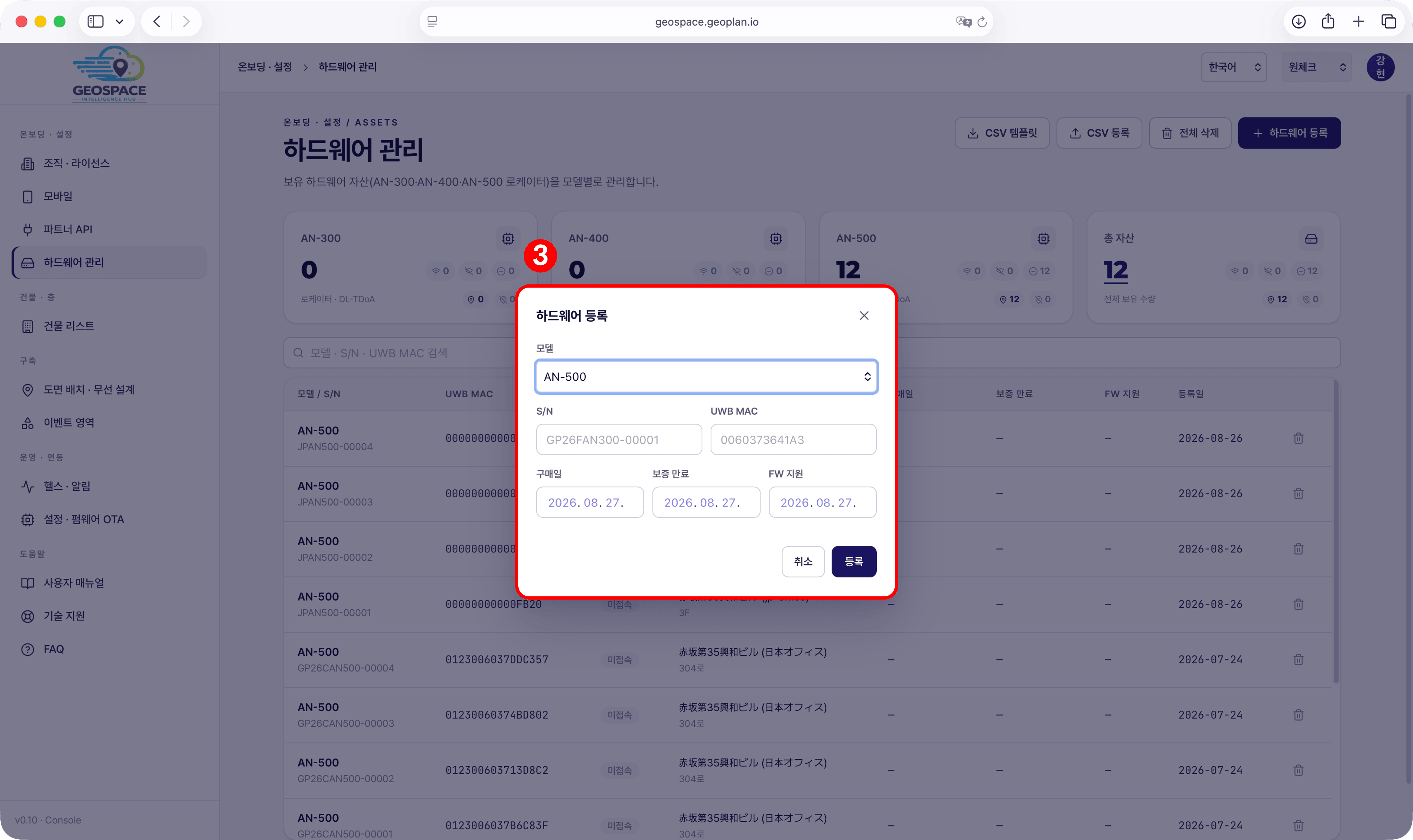 * **1** In the GeoSpace sidebar, go to **Onboarding · Settings → Hardware management**.
* **2** Press **\[+ Register hardware]** at the top right.
(Do this on a laptop or phone — with the device label in hand you can do it in the office ahead of time)
* **3 · Model** — select **AN-500**. (Mobile positioning currently supports AN-500 units only)
* **4 · S/N** — printed on the label on the back of the unit.
* **5 · UWB MAC** — printed on the label on the back of the unit.
* **6 · Purchase date · warranty expiry · firmware support** — fill these in, then press **\[Register]**.
To register several units at once, download the **\[CSV template]**, fill it in, and register them in bulk with **\[CSV import]**.
**One more thing before you install — mark the last 4 digits of the UWB MAC on the front of each anchor** (label sticker or masking tape).
If the units already shipped with that marking on the front, use it as is.
After installation the back label is out of sight, so in [Plan placement](/en/geospace/placement#1-place-on-the-plan)
you tell "which corner is which anchor" by those last 4 digits.
* **1** In the GeoSpace sidebar, go to **Onboarding · Settings → Hardware management**.
* **2** Press **\[+ Register hardware]** at the top right.
(Do this on a laptop or phone — with the device label in hand you can do it in the office ahead of time)
* **3 · Model** — select **AN-500**. (Mobile positioning currently supports AN-500 units only)
* **4 · S/N** — printed on the label on the back of the unit.
* **5 · UWB MAC** — printed on the label on the back of the unit.
* **6 · Purchase date · warranty expiry · firmware support** — fill these in, then press **\[Register]**.
To register several units at once, download the **\[CSV template]**, fill it in, and register them in bulk with **\[CSV import]**.
**One more thing before you install — mark the last 4 digits of the UWB MAC on the front of each anchor** (label sticker or masking tape).
If the units already shipped with that marking on the front, use it as is.
After installation the back label is out of sight, so in [Plan placement](/en/geospace/placement#1-place-on-the-plan)
you tell "which corner is which anchor" by those last 4 digits.
 ## 2. Anchor installation (physical)
Install the anchors at the **four corners** of the detection area. A mounting height of **2.4 – 3 m is recommended**,
and **closer to 3 m is better** (2 m minimum).
* **Wall mounting — the default for permanent installs**: fix with double-sided tape **on the wall, 2.4 – 3 m above the floor** (the wall, not the ceiling). It makes the height easier to reach,
and real deployments use this method too. In leased spaces, confirm in advance whether wall damage is acceptable.
**The order and orientation for mounting** — you cannot measure the height and stick the unit up at the same time on your own, so split it into two stages.
1. First measure the mounting height from the floor with a tape measure and **mark the wall in pencil** (all four anchor positions).
2. Mount the anchor at the mark — **front (the face with the LED window) facing into the store, cable connector facing down**, mounted vertically (the same orientation as the photo below). Get as close to the corner of the wall as you can. The back (the face with the S/N label) sits against the wall.
* **Tripod stands — for temporary installs and demos**: no wall damage, suitable for demos and short-term installs in leased spaces.
If placing on a desk, ensure a height of **2 m or more**.
## 2. Anchor installation (physical)
Install the anchors at the **four corners** of the detection area. A mounting height of **2.4 – 3 m is recommended**,
and **closer to 3 m is better** (2 m minimum).
* **Wall mounting — the default for permanent installs**: fix with double-sided tape **on the wall, 2.4 – 3 m above the floor** (the wall, not the ceiling). It makes the height easier to reach,
and real deployments use this method too. In leased spaces, confirm in advance whether wall damage is acceptable.
**The order and orientation for mounting** — you cannot measure the height and stick the unit up at the same time on your own, so split it into two stages.
1. First measure the mounting height from the floor with a tape measure and **mark the wall in pencil** (all four anchor positions).
2. Mount the anchor at the mark — **front (the face with the LED window) facing into the store, cable connector facing down**, mounted vertically (the same orientation as the photo below). Get as close to the corner of the wall as you can. The back (the face with the S/N label) sits against the wall.
* **Tripod stands — for temporary installs and demos**: no wall damage, suitable for demos and short-term installs in leased spaces.
If placing on a desk, ensure a height of **2 m or more**.
 Connect power (USB-C, 5V/3A) to each anchor, and secure any cable running across the floor with paper tape so nobody trips on it.
If someone catches a cable and pulls it out, that one anchor goes quietly dark and positioning quality drops.
When power is on, the LED window on the front lights up. Three readings are all you need.
Connect power (USB-C, 5V/3A) to each anchor, and secure any cable running across the floor with paper tape so nobody trips on it.
If someone catches a cable and pulls it out, that one anchor goes quietly dark and positioning quality drops.
When power is on, the LED window on the front lights up. Three readings are all you need.
 Avoid mounting on **metal surfaces** such as steel, iron, or aluminum. Radio interference can reduce positioning accuracy.
At this step, all you check on the LED is **whether it is lit** — whether positioning actually works is confirmed
in [Verification](/en/geospace/verify), after plan placement and the cluster are done.
## 3. Set the origin and measure coordinates
Before you set an origin, confirm that the **actual overall width and depth of the site** have been measured
(if you completed this in [Before you install](/en/geospace/site-survey#1-site-survey), use those values).
Before measuring coordinates, stand in the store and pick one **reference direction — "this way is up."**
This direction is called **true north**, but it has nothing to do with an actual compass bearing — **you decide it**.
Facing from the entrance into the store is usually the convenient choice. Once you have chosen, you use **the same direction all the way through** — plan upload, coordinate measurement, and the verification app.
Standing and facing the direction you chose, the **bottom-left corner (front left of you)** is the origin (0, 0).
X grows to the right, Y grows toward true north (ahead) — every coordinate is positive, so there are no sign mistakes when you type them in.
**Mark the origin on the floor with tape** (you will need to find it again later).
Avoid mounting on **metal surfaces** such as steel, iron, or aluminum. Radio interference can reduce positioning accuracy.
At this step, all you check on the LED is **whether it is lit** — whether positioning actually works is confirmed
in [Verification](/en/geospace/verify), after plan placement and the cluster are done.
## 3. Set the origin and measure coordinates
Before you set an origin, confirm that the **actual overall width and depth of the site** have been measured
(if you completed this in [Before you install](/en/geospace/site-survey#1-site-survey), use those values).
Before measuring coordinates, stand in the store and pick one **reference direction — "this way is up."**
This direction is called **true north**, but it has nothing to do with an actual compass bearing — **you decide it**.
Facing from the entrance into the store is usually the convenient choice. Once you have chosen, you use **the same direction all the way through** — plan upload, coordinate measurement, and the verification app.
Standing and facing the direction you chose, the **bottom-left corner (front left of you)** is the origin (0, 0).
X grows to the right, Y grows toward true north (ahead) — every coordinate is positive, so there are no sign mistakes when you type them in.
**Mark the origin on the floor with tape** (you will need to find it again later).
 You can point true north any way you like — **rotating it 90° so the side wall is up is equally correct.**
But if you change the direction, **the corner that becomes the origin changes with it, and the plan image has to be made with that direction up** as well.
You can point true north any way you like — **rotating it 90° so the side wall is up is equally correct.**
But if you change the direction, **the corner that becomes the origin changes with it, and the plan image has to be made with that direction up** as well.
 Measure each anchor's physical position relative to the origin (0, 0, 0) you set.
**1 m in the real world = 1 coordinate unit** (a 1:1 mapping), and Z is the mounting height (from the floor, for example 2.4).
* **How far you measure** — to the **point on the floor directly below the center of the anchor**, measured along the walls (not diagonally), width and depth separately.
If the anchor sits in a wall corner, you can use **the wall length as is**.
* **Accuracy** — ± 10 cm is enough. Tape-measure accuracy is not a problem.
* Even with only a tape measure and no laser distance meter, this method (corner origin) lets you measure everything.
Measure each anchor's physical position relative to the origin (0, 0, 0) you set.
**1 m in the real world = 1 coordinate unit** (a 1:1 mapping), and Z is the mounting height (from the floor, for example 2.4).
* **How far you measure** — to the **point on the floor directly below the center of the anchor**, measured along the walls (not diagonally), width and depth separately.
If the anchor sits in a wall corner, you can use **the wall length as is**.
* **Accuracy** — ± 10 cm is enough. Tape-measure accuracy is not a problem.
* Even with only a tape measure and no laser distance meter, this method (corner origin) lets you measure everything.
 **Coordinates work exactly like a ruler.** Depending on **where you line up the 0 mark**, the numbers at each end change, but the length of the thing you measured does not. A coordinate system is the same — wherever you put the origin (0,0), the room and the anchors stay where they are and **only the numbers** change.
**Example** — anchors installed at the four corners of a 10 m × 10 m space, with the bottom-left corner as the origin:
**Coordinates work exactly like a ruler.** Depending on **where you line up the 0 mark**, the numbers at each end change, but the length of the thing you measured does not. A coordinate system is the same — wherever you put the origin (0,0), the room and the anchors stay where they are and **only the numbers** change.
**Example** — anchors installed at the four corners of a 10 m × 10 m space, with the bottom-left corner as the origin:
 | Anchor position | X | Y | Z |
| -------------------- | -- | -- | --- |
| Bottom left (origin) | 0 | 0 | 2.4 |
| Bottom right | 10 | 0 | 2.4 |
| Top left | 0 | 10 | 2.4 |
| Top right | 10 | 10 | 2.4 |
### Alternative — the reference anchor method (sites where corners are hard to measure from)
If the room is not a clean rectangle, or columns and fixtures make measuring from the wall corners ambiguous,
you can build the coordinate system **around an anchor itself** instead of the walls.
| Anchor position | X | Y | Z |
| -------------------- | -- | -- | --- |
| Bottom left (origin) | 0 | 0 | 2.4 |
| Bottom right | 10 | 0 | 2.4 |
| Top left | 0 | 10 | 2.4 |
| Top right | 10 | 10 | 2.4 |
### Alternative — the reference anchor method (sites where corners are hard to measure from)
If the room is not a clean rectangle, or columns and fixtures make measuring from the wall corners ambiguous,
you can build the coordinate system **around an anchor itself** instead of the walls.
 1. Set anchor **#1 as the origin (0, 0)**.
2. **① Measure the #1 → #2 distance with a laser.** #2's coordinates are (measured value, 0) — **this direction becomes the X axis**.
3. For a rectangular layout you only need **② one more measurement, the depth**: #3 = (0, depth), #4 = (width, depth).
1. Set anchor **#1 as the origin (0, 0)**.
2. **① Measure the #1 → #2 distance with a laser.** #2's coordinates are (measured value, 0) — **this direction becomes the X axis**.
3. For a rectangular layout you only need **② one more measurement, the depth**: #3 = (0, depth), #4 = (width, depth).
 | Anchor | X | Y | Z |
| ------------------------------ | --- | --- | --- |
| AN-500 #1 (reference · origin) | 0 | 0 | 2.4 |
| AN-500 #2 | 7.1 | 0 | 2.4 |
| AN-500 #3 | 0 | 5.2 | 2.4 |
| AN-500 #4 | 7.1 | 5.2 | 2.4 |
Whichever way you measure, the rule for the next step is the same — when you enter the values in [Plan placement](/en/geospace/placement#1-place-on-the-plan),
you **have to add the offset from the plan image origin**.
**Checkpoints —** this step is complete once three things are in place.
1. **Four anchors registered** in GeoSpace **Hardware management**
2. **All four anchor LEDs lit** (not red)
3. **Four coordinate sets (X · Y · Z) recorded**, one per anchor — you enter these numbers as they are in the next step
## Next steps
Enter the coordinates you measured on the GeoSpace floor plan and apply a cluster.
| Anchor | X | Y | Z |
| ------------------------------ | --- | --- | --- |
| AN-500 #1 (reference · origin) | 0 | 0 | 2.4 |
| AN-500 #2 | 7.1 | 0 | 2.4 |
| AN-500 #3 | 0 | 5.2 | 2.4 |
| AN-500 #4 | 7.1 | 5.2 | 2.4 |
Whichever way you measure, the rule for the next step is the same — when you enter the values in [Plan placement](/en/geospace/placement#1-place-on-the-plan),
you **have to add the offset from the plan image origin**.
**Checkpoints —** this step is complete once three things are in place.
1. **Four anchors registered** in GeoSpace **Hardware management**
2. **All four anchor LEDs lit** (not red)
3. **Four coordinate sets (X · Y · Z) recorded**, one per anchor — you enter these numbers as they are in the next step
## Next steps
Enter the coordinates you measured on the GeoSpace floor plan and apply a cluster.